Week 2:- BiW Fixture Basics Challenge
Q.1. What is the process of project execution activity?
ANS. The process of execution activity are as below:
- RFQ received: RFQ stand for Request for Quotation. In this step customer gives his requirement, specification of the product or services we provided to our customer.
- 1st spec discussion meeting: After completing first step, the meeting will be carried out to discuss differnt things like technical, commercial offers , cost minimization and timeline ,etc.
- Offer submission: Outcome or result of above meeting will be documented and submitted to customer for feedback and review.
- LO/PO receipt: Purchase order will be sent by customer by reviewing offer letter submitted by company in above step.
- Schedule preparation: To complete project in time this is one of the important step. After receiving purchase order from customer proper schedule is created which consist of all the steps from RFQ to final hand over.
- BOM preparation: In this step Bill of Material is prepared according to the project.
- Design concept preparation: By considering customers requirement and specification, design will be prepared in this step and send to the customer for his approval.
- Custumor approval: Submitted design is check by customer, if design contain all the specificaton and requirement mentioned in RFQ then customer gives approval or gives some correction points.
- Detailing and drawing release: After receveiving approval detailing is starting of approved design and will be released for manufacturing.
- Manufacturing/BOP ordering: In this step manufacturing will be start and bought out parts like standard clamps, handles and motor, etc. will be ordered.
- Mechanical and Electrical assembly: All manufatured parts and BOP parts will be ordered in this step.
- Quality inspection: After completing assembly of all manufactured parts and BOP quality inspecion will be done. CMM (co-ordinate measuring machine) is used for quality inspection purpose.
- Internal trial and testing: To check operational feasibility such internal trial and testing will be carried out .
- Online trial: This online trial is done with the help of electrical connections and infront of customers.
- Packaging: Proper packaging is must to avoid damage during transportation.
- Dispatching: After completing above step our product dispatch to customers address.
- Installation as per layout: In this installation of fixture is done as per layout. This layout is designed by considering functionality, process sequence and applicaton of each part in fixture.
- Trails and training at customer: Trails and training will be given to the operators, staffs and engineers of customers to perform each and every actions on fixture like loading and unloading.
- Buy off meeting: Doubts and question of customer should be solve in this meeting.
- Final hand over:In this step fixture or product handed over to the customers.
Q.2. What are the types of joining processes?
ANS. Joining Process is used to join two or more parts with each other temporarily or permanently. Basically, there are two types of joining process:
I.Mechanical Joining Processes:
Mechanical Joining consists of following processes: Nut and bolts, screws, riveting and clamps. This mechanical joining processes are temporary or can be separeted or disassembled.
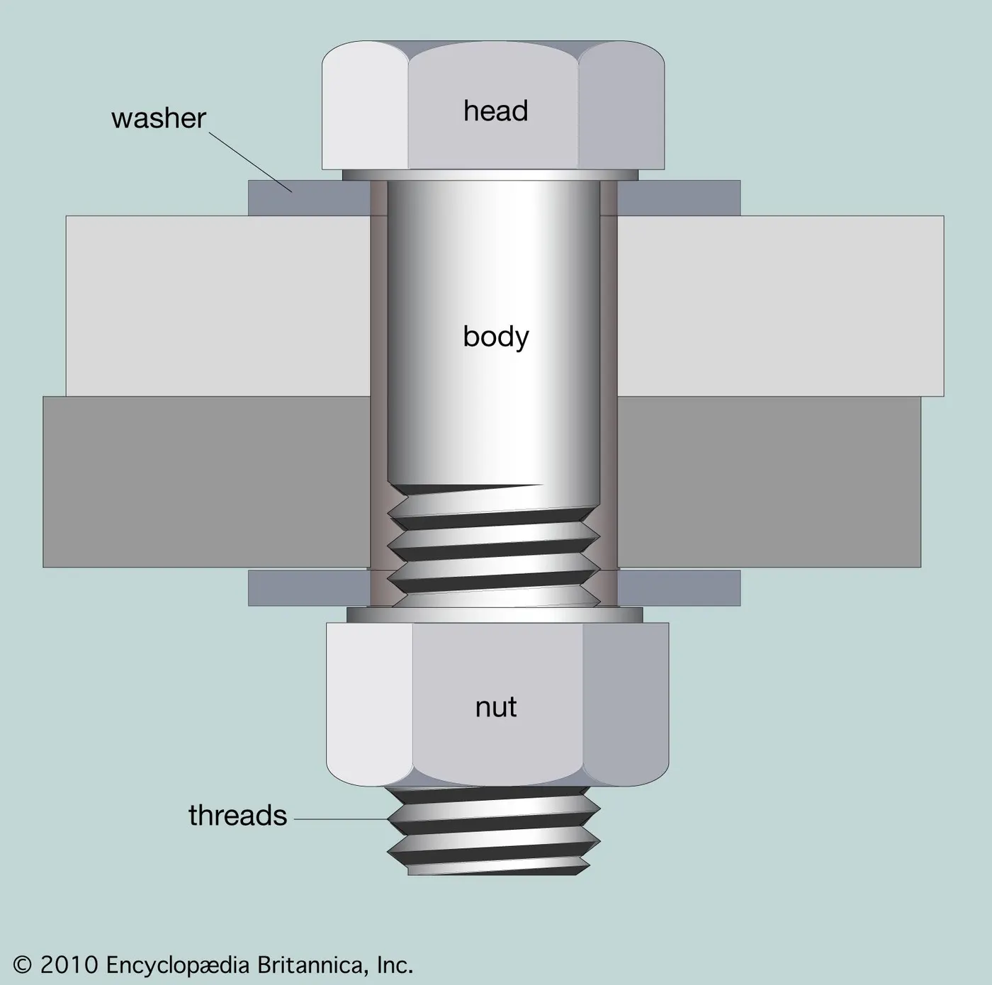
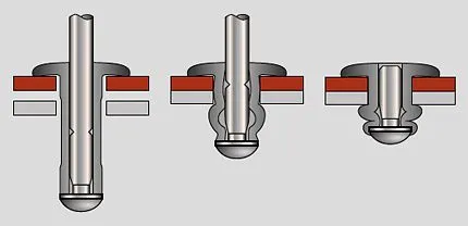
Nut & Bolt Rivets Clamps
II.Metallurgical Joining Processes: Different metallurgical joining processes are as below:
- Welding: It is one of the common metal joining processes which uses heat or pressure or both to melt the metal. There are diffferent types of welding processes like arc welding, resistance welding,etc.
- Brazing: Brazing is also a joining processes which uses filler material to create joint without melting base metal which is to be join.
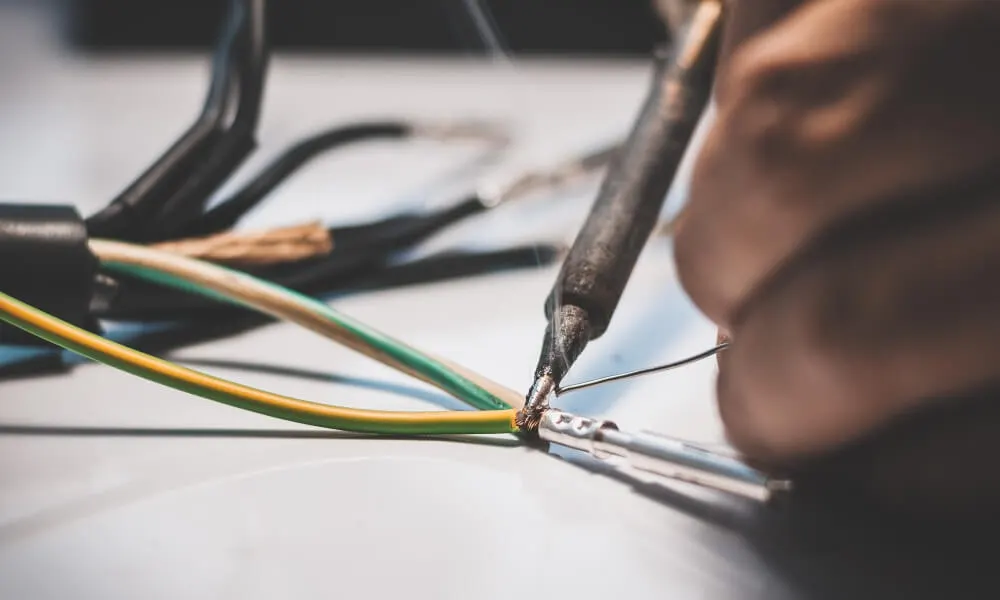
- Soldering: In this processes, thin wired filler material is used to create a joint. The filler wire is made up of tin-zinc, tin-lead and lead-silver, etc. Soldering required less temparature than brazing and welding.
- Adhesive Boding: In this type of joining process adhesive is used to join two different or same materials like metal to metal or metal to polymer, ec.
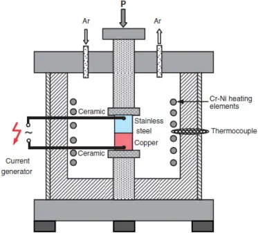
- Diffusion Bonding: It performs at higher temparature to deform the materials and to form joints between them. Diffusion bonding is solid state joining process.
Q.3. What is Resistance Welding & its application in the automotive sector?
ANS. Resistance Welding is type of welding in which joining of metal is take place by applying pressure and passing current between them. Advantage of resistance welding is no extra material is required to complete joining process and hence it is cost effective weldiing process. Heat required to melt the metal is generated due to resistance to flow of current is created between metal surfaces.. Types of resistance welding are as below:
1.Spot Welding:
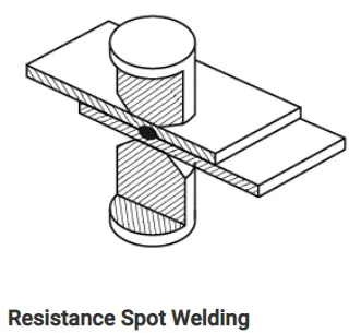
In spot resistance welding, joining is take place by passing current between two metal surfaces which is to be join and applying some pressure on these surfaces using elctrodes as shown in figure. Weld spot is created between metal parts as shown in figure. The number of spots are created between metal joining surfaces according to the application. The weld nugget size is usually depends on tip size of electrodes used.
Application:
- In automotive industry spot welding is large used to assemble automobile components.
- In manufacturing of domestic equipments
2. Seam Welding:
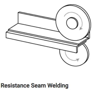
Seam welding is similar to that of spot welding process. The only differance is in seam welding is, pressure and current is applying with the help of elctrode wheels as shown in figure. In seam resistance welding process insted of spot, metal surface joins due to continuous weld seam as shown in diagram.
Application:
- In manufacturing of air or water tight containers, vessels and radiators
- In manufacturing of boilers and heat exchangers
3.Projection Welding:
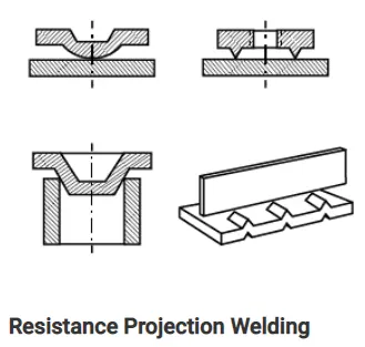
It is the type of resistance welding in which metal components are joins with the help of special kind of electrodes, applying pressure on these components. The electrodes used in this type of resistance welding is shown in diagram. The electrode used in this type welding having special shape or projetcion which fits in the shape of component.
Application:
- In electronics and electric sector projection welding is used.
- In manufacturing of sensors, valves and pumps etc.
- Also in automotive and construction industries
Q.4. What is fusion welding & types of fusion welding with its application in the automotive sector?
ANS. Fusion Welding is one of the welding technique in which two or more materials joins with application of heat. In this welding type material heated upto its melting point for perfect welding. Different types of fusion welding are:
1.Manual Metal Arc Welding:
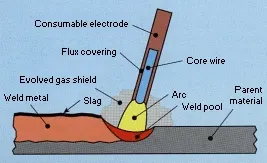
Its is also known as Shielded Metal Arc Welding. This consist of consumable electrode having coating of flux. AC or DC power supply is connected to a electrode which forms or which created arc between materials to be welded and electrode results into melting of both electroden and material. Flux coating on electrode also melts and forms shielding gas and layer of slag on molten metal to protect welding joint form atmospheric contamination.
2. Metal Inert Gas Welding:
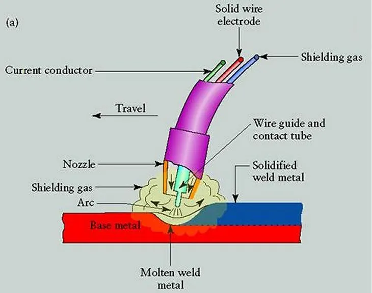
Its is also known as Gas Shielded Metal Arc Welding. In MIG welding, consumable wire electrode is used. Arc is created between this consumable wire eletrode and materials on which welding joint to be takes place. Inert shielding gas is also used in this type of welding to protect weld joint from air contaminaton which form oxidation on welding joint.
3. Tungstan Inert Gas Welding:
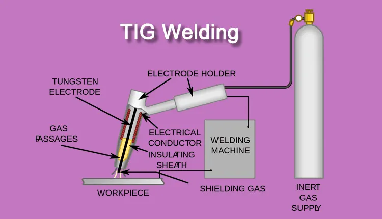
Its is also known as Gas shielded Tungstan Arc Welding. In TIG welding, non-consumable tungstan electrode is used. Also, inert shielding gas in used to form defect free weld joint by preveting oxidation reaction which take place due to air contamination.
4. Plasma Arc Welding:
Plasma Arc Welding is similar to that of Tungstan Arc welding. The only differance is in TIG welding arc is created between non-consumable tungstan electrode and workpiece where as in Plasma Welding arc is generated between torch and non consumable electrode. In this type of welding electrode in placed within torch and hence separated from shielding gas.
Q.5. What is the 3-2-1 principle?
ANS. 3-2-1 principle of location or 6-pin or 6-point location principle is very useful while designing fixture. It is very necessary to locate component in the fixture having no movement and this is possible only if all 12 degree of freedom of component is restricted. 12 degrees of freedom are as below:
- + X direction
- - X direction
- + Y direction
- - Y direction
- + Z direction
- - Z direction
- Clockwise along X axis
- Counter-clockwise along X axis
- Clockwise along Y axis
- Counter-clockwise along Y axis
- Clockwise along Z axis
- Counter-clockwise along Z axis
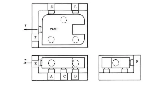
In above example, workpiece is locating with the help of 6 locating pins(A,B,C,D,E and F) which prevents 9 degrees of freedom. Rest 3 degrees of freedom are restriced by providing external forces using clamping. These clamps are used to load or unload workpiece from fixture easily and without any difficulities to worker or operators.
Q.6. Define Body coordinate system?
ANS. Simply, Co-ordinate system is the system which consist of planes, lines and points to specify or mention the position and alignment of object placed or assume in that system. In automotive BIW fixture design Body Co-ordinate System in also known as 'Car line' or 'Body line'.
In fixture design, every units like clamping, location or rest unit are specify with respect to X,Y and Z co-ordinates. This will also help while assembly of fixture to identify its position. Using 3 planes all parts are identified and these planes are as below:
X= Longitudinal direction (FOL- Front O Line)
Y= Transverse direction (COL- Center O Line)
Z= Vertical direction (B- Bottom O Line)
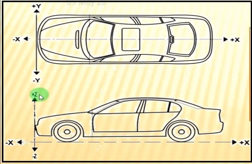
The origin of body co-ordinate system is located at front of the vehicle as shown in above figure where OX represents lenght of car, OY represents width of car and OZ represents height of car.
Q.7. Elaborate Body plane system & its essentials.
ANS. Basically, Body Plane system are imaginary system which consist of planes (XY, YZ and ZX), lines (X, Y and Z) and points to identify automotive parts or other components. This is widely used in automotive sector for referance and its essentials are as below:
- To identify every parts in vehicle
- This system will help while designing BW fixtures or some other things
- It helps while inspection or quality checking.
- Body plane system is very useful in assembly work.
- This system is consider as standard system.
- While designing each and every parts or units in fixture body plane system plays impoertant role to mentioned that parts or units co-ordinates with respect to body planes.