Week 2:- BiW Fixture Basics Challenge
- What is the process of project execution activity?
PROCESS OF PROJECT EXECUTION ACTIVITY:
- The above figure shows the process involved in process execution activities. It is a general activity that is involved in BIW fixture & Tooling.
- It is the starting phase of every project.
- It starts with the basic requirements/RFQ we received from the customer.
- As shown in the figure there are various steps involved in project activities, They will be explained in detail below.
1. RFQ:
- RFQ – Request for Quotation.
- In this where the customer gives the requirement/specifications in detail for the given projects in the form of data or documents.
- Also, the customer specifies its technical offer, commercial offer, etc, how the project will be executed & the timeline of the project also will be mentioned.
2. FIRST SPEC: DISCUSSION MEETING:
- After RFQ received, Technical offer, commercial offer, a timeline of the project, etc, will be discussed and prepared from outside.
- In this time required for data study, 3D design concept, simulation validation, quality check, 2d drawing release, bought-outs, manufacturing, assembly, installation & commissioning will be discussed and prepared in the technical offer.
- Based on the technical offer, the commercial offer will be finalized.
3. OFFER SUBMISSION:
- After the finalization in the meeting, the offers will be submitted to the customer end. The customer will arrange to get an offer from other suppliers too.
- Based on the technical, cost, quality, standard, and name in the industries, the customer will be finalizing the offer.
4. LOI/PO RECEIPT:
- After an offer has been finalized customer will be releasing the LOI/PO (Purchase Order). Once PO is released, we have to start the work.
- After getting the PO from the customer, we have to prepare the schedule.
5. SCHEDULE PREPARATION:
- Once the PO released from the customer, we will be working on the preparation of the schedule which should be matched our planned commitment in the technical offer/customer required time.
- Schedule preparation is nothing but dividing the different activities like kick-off meeting, design data study, DAP, simulate, Quality check 2D detailing, drawing check, Release of BOM, Manufacturing, bought outs of electrical & mechanical components, Assembly of the fixture, paint, trial run out, installation and commissioning at the customer end, etc.
- These activities will be traced in the schedule preparation chart.
- The date-wise schedule should be matched the committed date. Otherwise have to revise the schedule and prepare accordingly by discussing it in the meetings.
6. BOM PREPARATION:
- Bill of materials like cylinders, motors, etc, which are required for the project are prepared.
7. DESIGN CONCEPT PREPARATION:
- Before design concept, we have to study the data of consumer requirements thoroughly which is carried out in design data study activities.
- During the design data study, we will proceed with rough sketches to get a flow while designing concepts.
- The concept preparation would include the process like load act on panels, clamping process, which spot should be welded first, travel of the gun.
- In this concept preparation, we should conceptualize the basic data like spot plan, cycle time, etc,
- The weld gun should not collapse while traveling, so by considering this have to make a concept preparation.
- To avoid collapses of weld guns or robots during traveling, a spot plan will be done at the initial stage.
- In design concept preparation, the design of the layout is been prepared at a very initial level which gives the information of placements of robots and fixtures.
- Spot plan should be taken into consideration during concept design preparation
- The spot plan clears us that how many robots are to be used and the sequence of the spot will be decided along with which robot will be cover certain spot places.
- Also, the cycle time should be considered while preparing the concept design. To calculate the cycle time, we should go to the cycle time study.
- Cycle time study includes min per shift, No. of shifts, No. of days per year, No. of component per year, the total number of minutes.
- Cycle time study includes min per shifts, no. of shifts, no of days per year, no of component per year, the total number of minutes, efficiency, Total no of seconds, take time seconds, average time per spot, total no of spot, no of robots placed. From the cycle time study, we can get time taken per spot, time is taken for a single component, efficiency of production. If the efficiency is not satisfied, we have to do some reconsideration in the design.
8. CUSTOMER APPROVAL:
- It is also known as the Design Approval Process (DAP).
- After design concepts, the customer will review the design concepts.
- If the design needs to be made simple or some other correction needs to be done in concept design will be discussed and after meeting the requirement of the customer, they will give approval to the design to go on with further activities.
9. DETAILING & DRAWING RELEASE:
- Once the customer approved the process, the detailing of the fixture parts which is to be manufactured has been done by giving appropriate dimensions and GD&T symbols.
- All the dimensions which are necessary for manufacturing should be included with GD&T in the drawing before releasing the drawing to the manufacturing team.
10. MANUFACTURING/BOP ORDERING:
- The mechanical & electrical parts like sensors, cylinders, etc, which needs for a fixture are ordered as per design specifications.
11. MECHANICAL / ELECTRICAL ASSEMBLY:
- After the materials ordered received to our end. The quality will check the working conditions and technical specs, which meets our requirement.
- After the quality check, the mechanical & electrical parts are assembled as per design.
12. QUALITY INSPECTION:
- After the assembly again the quality check is done.
- In all dimensions, positional accuracy, coordinates are checked using CMM.
13. INTERNAL TRIAL:
- After QC check, internal trials are made to check the operation of the fixture.
- It is the first trial taken in-house, so we will see by putting the assembly in the fixture whether the seating of assembly/panel suited correctly, whether the clamping operation is done properly, also whether the pins are getting into the holes, etc.
14. ONLINE TRIAL:
- The trail will be done automatically made through the control panel. The process sequence of operation is checked as by the designed way.
15. PACKAGING:
- To avoid damage, occur in the fixture while transportation which may also lead to affect the Aesthetic look & proper function of fixture packaging has been done.
- After the trials taken have to get the QC confirmation whether the panels met the standards/specs, given by the customer also whether the fixture meets the customer standards.
- After approval of QC, the packaging is been done as per standards. Certain companies follow certain packaging standards, So the packaging should be one as per customer standards.
16. DESPATCH:
- After the fixture has been packed for delivery as per standards. It’s been despatched to the customer.
17. INSTALLATION AS PER LAYOUT:
- As we discussed in design concept preparation, the design of the layout are been prepared at a very initial level which gives the information of placements of robots and fixtures.
- According to the design, the installation & commissioning team will install the fixtures.
18. TRAILS & TRAINING AT CUSTOMER:
- Production trials will be taken at the customer end.
- During the technical offer, we will be confirmed that the n-number of assemblies will be produced within 8hrs/12hrs shifts. So in customer trial, we have to achieve the confirmed quantity of assemblies.
- Once it is achieved training will be given to the operator, staff, engineers who involved in this process. The sequence of the working process by the fixture will be explained in detail.
- The checkpoints which have to be done after placing the panels into the fixture will be made clear to them.
19. BUYOFF MEETING:
- After trials and training at the customers' end, the buy-off meeting will be held.
- In this meeting customer will give reviews about the fixtures, sometimes a customer may need/feels better to do some additional work also. It will be discussed and finalize in the meeting.
20. FINAL HANDOVERS:
- The fixture and the documents support the fixtures/production will be handed over.
- Documents like clamp validation documents, ergo sheets, BOMs, charts will be delivered and handed over to customers. Documents will play a vital role in the industry. We should always have proof of our work done. The sequence of quality of work will be seen through the documents.
- Every automobile industry will follow some standards to maintain documents as per ISO, IATF.
- Now every automobile industry/vendor/supplier is maintaining the documents as per IATE (International Automotive Task Force).
- IATE – The international Automotive Task Force is a group of automotive manufactures which aims at providing improved quality products to automotive customers worldwide.
- 2.What are the types of joining processes?
- In the context of Body-in-White (BIW) manufacturing, which refers to the assembly of the car body structure, several joining processes are commonly used. The specific joining processes employed can vary depending on the materials being joined and the desired characteristics of the final assembly. Here are some of the types of joining processes used in BIW:
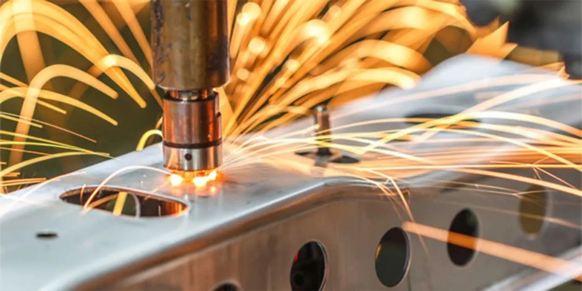
- 1.Spot Welding: Spot welding is widely used in BIW assembly. It involves the application of heat and pressure to join two metal sheets by creating localized welds at specific points using electrical resistance.
-
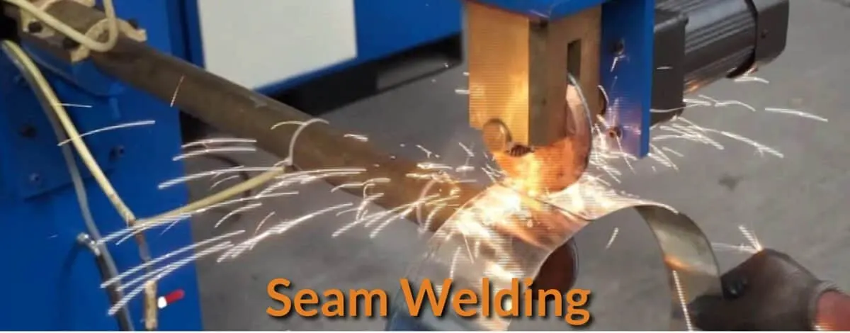
2.Seam Welding: Seam welding is similar to spot welding but creates a continuous weld along the length of a joint. It is commonly used for joining components in the BIW, such as body panels and structural reinforcements.
-
3.Laser Welding: Laser welding utilizes a high-energy laser beam to melt and fuse metal components together. It provides precise control and is often used for joining thin or complex-shaped components in the BIW.

-
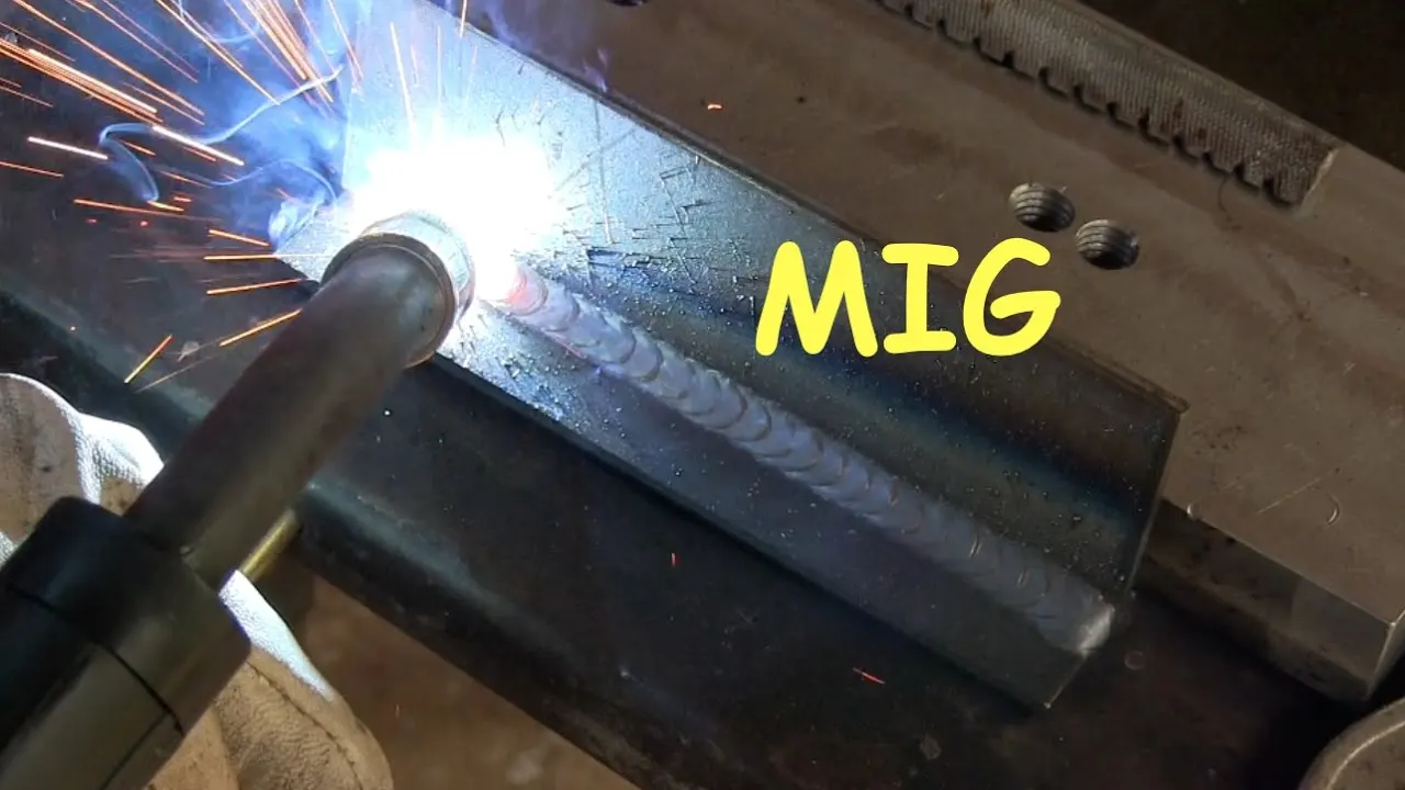
4.MIG/MAG Welding: Metal Inert Gas (MIG) or Metal Active Gas (MAG) welding uses a consumable electrode wire and a shielding gas to create an arc between the electrode and the workpiece. It is versatile and suitable for a variety of metal joining applications in the BIW.
-
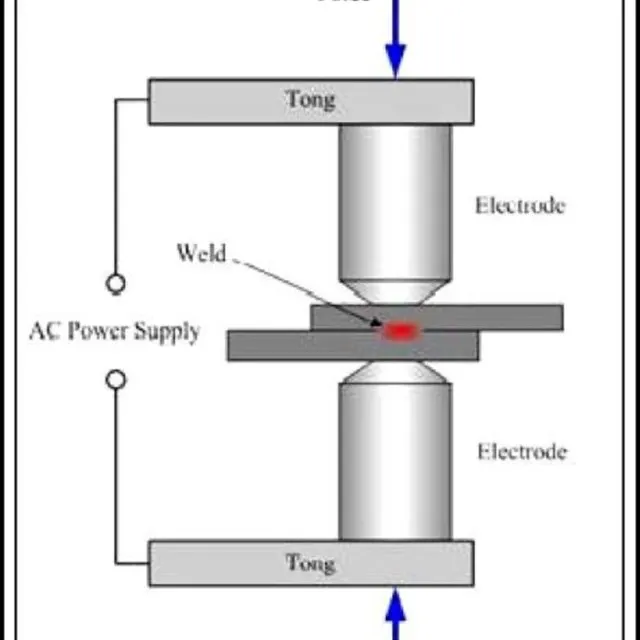
5.Resistance Spot Riveting: Resistance spot riveting is a process that combines elements of spot welding and riveting. It involves using a rivet to join two or more metal sheets together by applying heat and pressure through resistance welding.
-
6.Adhesive Bonding: Adhesive bonding involves the use of adhesives to join components together. It is often used in BIW assembly to join dissimilar materials or provide vibration damping and noise reduction.
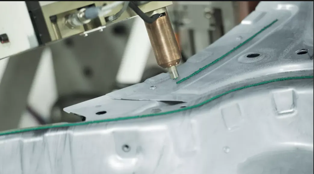
- 7.Mechanical Fastening: Mechanical fastening methods, such as riveting, screws, and clinching, are sometimes used in BIW assembly. These methods mechanically secure components together without using heat or adhesives.
-
8.Friction Stir Welding: Friction stir welding is a solid-state joining process that uses a rotating tool to generate heat and plasticize the material, which is then forged together to form a joint. It is commonly used for joining aluminum components in the BIW.
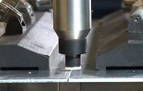
9.Manual Metal Arc Welding
In Manual Metal Arc welding(MMA or MMAW) or Stick Welding uses an electrode which is flux coated and workpiece to create a arc. Both rod and surface material melt to create a weld.- 10.Gas Shielded Metal Arc Welding(Metal Inert Gas(MIG))
It is an arc welding technique in which a consumable electrode is used to weld two metal sheet components together. MIG uses a consumable electrode, DC or AC Supply, Inert Gas Supply.
Shielding gas is used to prevent the weld pool from contamination. Contamination can affect the quality of weld. Shielding Gas also acts as a carrier of Filler Metal in the form of droplets. Shielding gases include 100% CO2 or a mixture of CO2 and Argon. A 75 percent Argon And 25 Percent combination of inert gas acts best for the visual quality of weld.
11.Resistance Projection welding
It is used to weld sheet metal components with projections. These projects can be natural or manually made. Currrent passes through the projection part of sheet metal in contact and melts it and pressure is applied using specially designed electrodes depending on the shape of workpiece. It is mainly used for fixing autobody components eg. Weld nuts
12.
Arc Welding
Arc Welding uses an electrode(consumable/non-consumable) to weld two components. The arc produced between the electrode and workpiece using AC or DC supply welds the two components together.
13.Bolting
Bolting is a joining process which is used for assembly of different parts that are to be joined temporarily and whose joints require periodic maintenance. On bolting joints, mainly two kinds of loads act, shear and tensile. In this process, (bolt/screw) (and/or nut) are used to join the two parts. In case of joining with help of a screw, one of the two parts to be joined has a clear hole and the other part has a tapping. Both the clear hole and the tapping are kept concentric for the screw to tighten accurately an easily. For the ease of installation and removal, bolting access is an important factor that needs to be taken care of. Spring washer is place between the nut and the bolt for the assembly to keep a tight fit against each other and to prevent loosening due to vibrations in the fixture.
There are three types of Bolting Joints:
1.Screw Joint
2.Bolted Joint
3.Stud joint
14.Hemming:
Hemming and seaming are two similar metalworkingprocesses in which a sheet metal edge is rolled over onto itself. Hemming is the process in which the edge is rolled flush to itself, while a seam joins the edges of two materials.
3.What is Resistance Welding & its application in the automotive sector?
Resistance welding:
Resistance welding is a joining process that involves the application of heat and pressure to join metal components together by creating localized electrical resistance. The heat is generated by passing an electric current through the workpieces, and the pressure is applied to ensure proper contact and fusion of the materials. The resistance welding process does not require any additional filler materials or flux.
In the automotive sector, resistance welding is widely used in the manufacturing of vehicles, particularly in the Body-in-White (BIW) assembly. Here are some applications of resistance welding in the automotive sector:
1.Spot Welding: Spot welding is the most commonly used resistance welding technique in the automotive industry. It is used to join overlapping metal sheets in various parts of the car body, including body panels, frame members, and structural reinforcements. Spot welding provides a strong and efficient joint, and it is capable of high-speed production.
2.Seam Welding: Seam welding is another resistance welding process used in automotive manufacturing. It involves creating a continuous weld along the length of a joint, typically used for joining long metal sheets or producing watertight and airtight seals. Seam welding is often employed in the assembly of fuel tanks, exhaust systems, and other fluid-carrying components.
3.Projection Welding: Projection welding is utilized for joining components with small projections or embossed features. It involves applying pressure and current to the projections, creating localized heating and fusion. Projection welding is commonly used in the assembly of automotive brackets, clips, and other small components.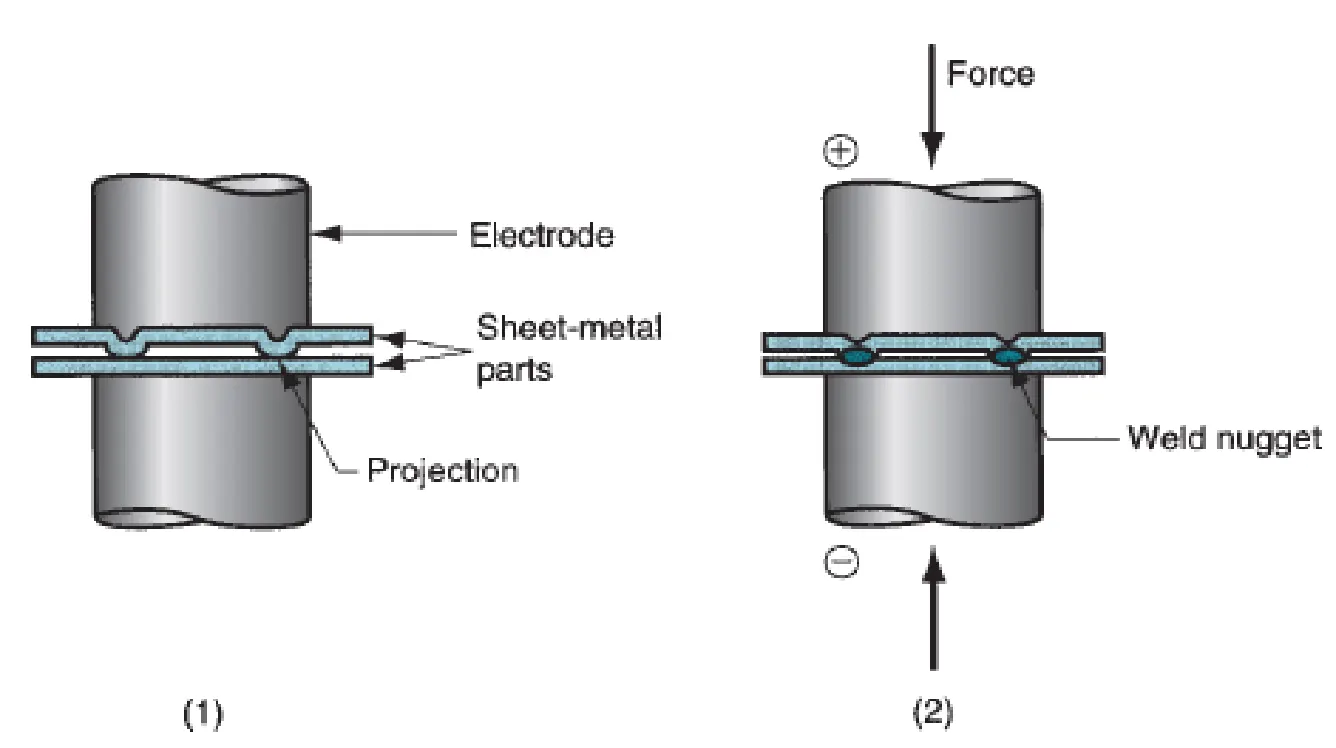 4.Flash Butt Welding: Flash butt welding is employed for joining thick metal sections, such as axles, suspension components, and chassis parts. It involves bringing the ends of the workpieces into contact, passing a high electric current through them to create intense heat, and then forging them together under pressure.
5.Upset Welding:
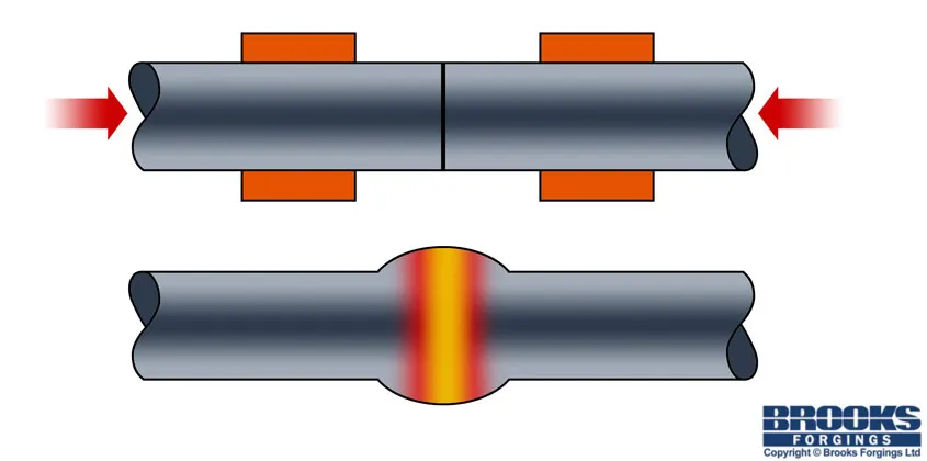
- Like other Resistance Welding Processes, Upset Welding uses heat generated by resistance to the flow of welding current, as well as force to push the workpieces together, applied over a defined period of time. While similar to Flash Welding, in Upset Welding the workpieces are already in firm contact with one another, so no flashing occurs. Pressure is applied before the current is started, and is maintained until the process is complete.
Resistance welding offers several advantages in the automotive sector:
-
Efficiency: Resistance welding is a rapid process, allowing for high-speed production in automotive assembly lines, improving productivity and reducing manufacturing costs.
-
Strength and Durability: The resulting welds from resistance welding are strong and durable, providing reliable joints that can withstand the stresses and loads experienced by automotive components.
-
Automation and Control: Resistance welding can be easily automated and integrated into robotic systems, providing precise control over the welding process and ensuring consistent quality.
-
Clean and Environmentally Friendly: Resistance welding does not require the use of additional filler materials or flux, making it a clean process with minimal environmental impact.
Overall, resistance welding plays a crucial role in the automotive sector, enabling efficient and reliable joining of metal components in the production of car bodies, frames, chassis, and various other automotive structures.
4.What is fusion welding & types of fusion welding with its application in the automotive sector?
Fusion welding:
Fusion welding is a type of welding process that involves the melting and fusion of base materials to create a strong joint. In fusion welding, heat is applied to the workpieces, causing them to melt and then solidify, resulting in a permanent bond between the components. The molten material may be supplemented with a filler material, depending on the welding process and the requirements of the joint. Fusion welding is widely used in the automotive sector for various applications.
Types of fusion welding with its application :
1.Gas Metal Arc Welding (GMAW/MIG): Gas Metal Arc Welding, also known as Metal Inert Gas (MIG) welding, is a widely used fusion welding process in the automotive industry. It involves the use of a consumable wire electrode that is continuously fed through a welding gun, along with a shielding gas to protect the weld pool from atmospheric contamination. GMAW/MIG welding is commonly used to join body panels, frame components, and other structural parts in automotive manufacturing.
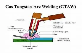
 2.Gas Tungsten Arc Welding (GTAW/TIG): Gas Tungsten Arc Welding, also known as Tungsten Inert Gas (TIG) welding, is another commonly used fusion welding process in the automotive sector. It utilizes a non-consumable tungsten electrode and a shielding gas to protect the weld area. GTAW/TIG welding provides precise control over the welding process and is often used for welding thin materials, such as exhaust systems, fuel tanks, and specialized automotive components.
3.Resistance Spot Welding (RSW): Resistance Spot Welding is a fusion welding process that uses electrical resistance to generate heat and create welds at specific points. It is extensively used in the automotive industry for joining metal sheets and panels. RSW is known for its speed, efficiency, and ability to produce high-strength welds. It is widely employed in the assembly of car bodies, frame structures, and other components that require strong and reliable joints.
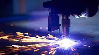
4.Laser Welding: Laser welding is a fusion welding technique that utilizes a high-energy laser beam to melt and fuse materials together. It offers precise control, minimal heat input, and high welding speeds. Laser welding is used in the automotive sector for joining various components where high accuracy, minimal distortion, and aesthetic appeal are important. It finds applications in areas such as body-in-white assembly, powertrain components, and suspension systems.
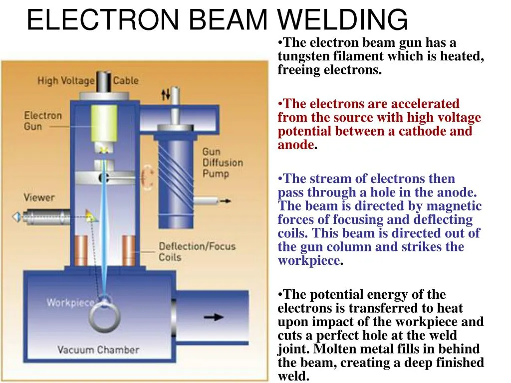
5.Electron Beam Welding (EBW): Electron Beam Welding is a fusion welding process that uses a high-velocity beam of electrons to create the weld. It is a highly precise and controlled process that produces deep penetration welds. EBW is employed in the automotive industry for applications such as joining transmission components, engine parts, and other critical assemblies that require high strength and integrity.
 These are some of the common fusion welding processes used in the automotive sector. The choice of welding process depends on factors such as the materials being joined, joint requirements (strength, aesthetics, etc.), production efficiency, and cost considerations. Welding plays a crucial role in the manufacturing of automotive components and structures, ensuring the integrity and durability of the final product.
5.What is the 3-2-1 principle?
3-2-1 principle is used for the design of the fixtures
- For a fixture designer, the major portion of design time is spent deciding how to locate the workpiece in the fixture.
- You know that any free body has a total of twelve degrees of freedom as below:
6 translational degrees of freedom: +X, -X, +Y, -Y, +Z, -Z And
6 rotational degrees of freedom:
- Clockwise around X-axis (CROT-X)
- Anticlockwise around X-axis (ACROT-X)
- Clockwise around Y-axis (CROT-Y)
- Anticlockwise around Y-axis (ACROT-Y)
- Clockwise around Z-axis (CROT-Z)
- Anticlockwise around Z-axis (ACROT-Z)
-
To make sure the proper fixing of the part we need to restrict all 12 degrees of freedom of the workpiece. The major portion of the time of BIW fixture designer is spent deciding how to fix these all DOF.
PRIMARY LOCATOR:
First, the three locators or supports are placed under the workpiece. It will be positioned on the primary locating surface also known as a datum. It will restrict 5 degrees of freedom.
- Axial Movement downward along Z-axis ( No.6 in Fig 1 )
- Rotation about the X & Y axis ( No. 7, 8, 9 & 10 in Fig 1)
SECONDARY LOCATOR:
The next two locators are normally placed on the secondary surface, restricting an additional 3 degrees of freedom.
- Axial movement along the Y+ axis ( No.3 in Fig 1 )
- Rotation about the Z-axis ( No. 11 & 12 in Fig 1 )
TERTIARY LOCATOR:
This locator is positioned at the end of the part. It restricts 1 degree of freedom
- Axial movement along the X-axis ( No.2 in Fig 1)
- All these 6 locators will restrict a total of 9 degrees of freedom. The remaining 3 degrees of freedom ( 1, 4 & 5 ) will be restricted by the clamps.
- To minimize the time consumption in assembly and disassembly, Have to use minimum numbers of pins to arrest a maximum number of degrees of freedom.
- The jig and fixture are tools used for holding the workpiece in a correct location for mass production. Various types of fixtures (like drilling fixtures, milling fixtures, and welding fixtures) are used in industry. The 3-2-1 method is the fundamental principle for all types of fixture design.
A body coordinate system, also known as a body-fixed coordinate system or local coordinate system, is a reference frame or set of axes that is fixed or attached to a specific object or body. It is used to describe and measure the position, orientation, and motion of that object relative to its own structure. In other words, a body coordinate system is a coordinate system that moves and rotates with the object it is attached to.
Key characteristics of a body coordinate system include:
Origin: The origin of the coordinate system is typically located at a specific point within or on the body, serving as the reference point for all position measurements.
Axes: Three mutually perpendicular axes (often labeled as X, Y, and Z) are defined relative to the body. These axes are aligned with specific directions or orientations on the body itself.
X-Axis: Often aligned with the longitudinal axis or another relevant direction on the body.
Y-Axis: Perpendicular to the X-axis and aligned with another relevant direction.
Z-Axis: Perpendicular to both the X and Y axes, completing the three-dimensional coordinate system.
Body coordinate systems are commonly used in various fields, including physics, engineering, biomechanics, robotics, and aerospace. They allow for the precise description of an object's position and orientation as it moves or rotates. Different objects may have their own unique body coordinate systems, depending on their shape and function.
7.Elaborate Body plane system & its essentials.
BODY PLANE SYSTEM:
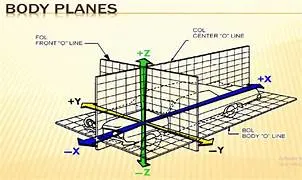
- Body planes are the reference plane in an automotive car. These planes are used to define the GD & T of all car parts in a automotive domain.
- Body planes are three mutually perpendicular imaginary planes. These are generally considered to be present at the driver position or sometimes at the engine location or at the front end of the car depending on the customer.
- The measurements from the body planes to the parts are called as body line dimension.
These body planes are called as
- FOL Front “O” line.
- COL Centre “O” line
- BOL Body “O’ line
- The measurement along FOL or X-axis is called as F/A Frontaft.
- The measurement along COL or Y-axis is called as C/C Cross car.
- The measurement along BOL or Z-axis is called as U/DUP down.
In below figure origin is somewhere below driving sheet as it depends or changes from customer to customer. But axis system is commonly same.
Bodyline dimensions are essential for the reasons stated below,
- It defines the exact position of each product in the vehicle w.r.t. a fixed origin.
- It ensures flawless design for assembly.
- While designing lines, all the designs are carried out relative to the bodyline, viz, fixture, turn table etc.
- It assists in easy location of different parts in a vehicle.
- It aims in creating a standardized system.
- It assists in quality checks.
These are basic essential thing that body line dimension would help in BIW. It could help in designing lines like welding lines, assembly lines or car body through fixture & turntable etc. This help in designing every tools. Particular assembly or parts are designed w.r.t body lines or an axis system or car line also helps in quality while doing CMM of that system. CMM is basically done with the help of coordinate. It has relate particular fixture with that car part, because that dimension, coordinates of hole & pin should match so it will help in quality check also. We just give co-ordinates that belong to that hole both coordinate should match. With this matching means quality is approved. Below figure shows some example.
Below fig show use of X plane to define the length of car.
Below figure show use of Y plane to define width of car.
Below figure shows use of Z plane to define height of car.