Week 2:- BiW Fixture Basics Challenge
1)What is the process of project execution activity?
PROCESS OF PROJECT EXECUTION ACTIVITY:
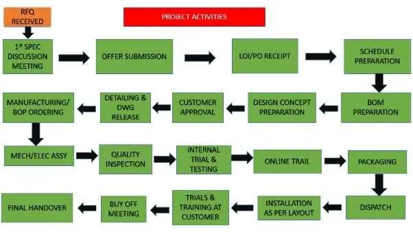
* The above figure shows the process involved in process execution activities.
* It is a general activities which is involved in BIW fixture & Tooling.
* It is a starting phase of every project.
* It starts with basic requirements/RFQ we received from customer.
* As shown in the figure there are various steps involved in project activities, They will be explained in detail below.
1. RFQ:
* A request for quotation (RFQ) is a business process in which a company or public entity requests a quote from a supplier for the purchase of specific products or service. RFQ generally means the same thing as call for bids (CFB) and Invitation for bid (LFB).
* In this where customer gives the requirement/specification in detail for the given projects in the form of data or documents.
2. FIRST SPEC, THE DISCUSSION MEETING:
* After RFQ received, the Technical offer, the commercial offer, the time line of the project, etc., and will be discussed and prepared from outside.
* In this time required for data study, 3D design concept, and Simulation validation, quality check, 2D drawing release, Bought outs, manufacturing, Assembly, installation & commissioning will be discussed and prepared in the technical offer.
* Based on technical offer, commercial offer will be finalized.
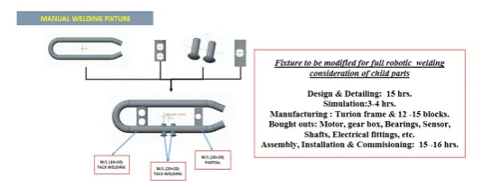
FIG . Basic example of Technical offer for manual welding
3. OFFER SUBMISSION:
* After the finalisation in the meeting, the offer will be submitted to costemer end.
* Customer will arrange to get offer from other suppliers too.
* Based on the technical, cost, quantity, standard and name in the industries the costemer will be finalized the offer.
4.LOI/PO RECEIPT:
* After offer has been finalized customer will be releasing the LOI/PO(purchase order).
* Once PO is realese we have to start the work.
* After PO from the customer we have to prepare the schedule.
5. SCHEDULE PREPARATION:
* Once the PO released from customer we will be working on preparation of schedule which be matched our planned commitment in the technical offer / customer required time.
* Schedule preparation is nothing but dividing the different activities like kick off meeting, design data study, DAP, Simulate, quality check, 2D detailing, Drawing check, release of BOM, Manufacturing, Bought outs of electrical & mechanical components, assembly of fixture, paint, trial run out, installation and commissioning at customer end etc,
* These activities will be traced in the schedule preparation chart.
* The date wise schedule should be matched the commited date. Otherwise have to revised the schedule and prepare accordingly by discussing in the meetings.
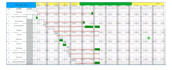
Figure . Example of schedule preparation chart
6. BOM PREPARATION:
* Bill of materials like cylinders, motors,etc., which is required for the project are prepared.
7. DESIGN CONCEPT PREPARATION:
* Before design concept, we have to study the data of consumer requirement throughly which is carried out in design data study activities.
* During design data study, we will be proceed with rough sketches to get a flow while designing concepts.
* The concept preparation would include the process like load act on panels, clamping process, which spot should be welded first, travel of the gun.
* The weld gun should not collapse while travelling, so by considering this have to make a concept preparation.
* To avoid collapses of weldgun or robots during travelling, spot plan will be doneat initial stage.
* In design concept preparation, the design of the layout are been prepared at very initial level which gives the information of placements of robots and fixtures.
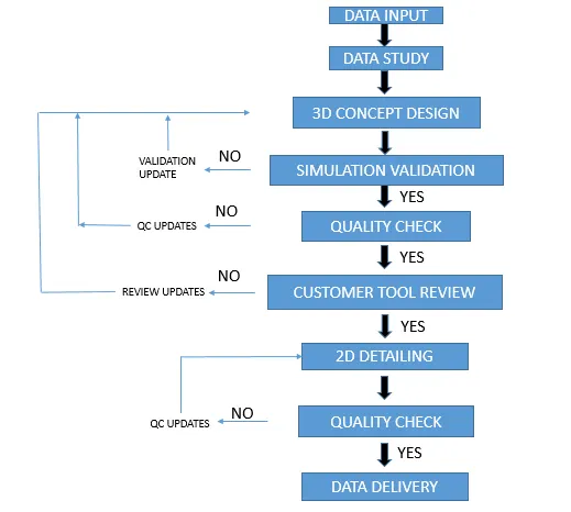
FIG 2. Process involved in Design
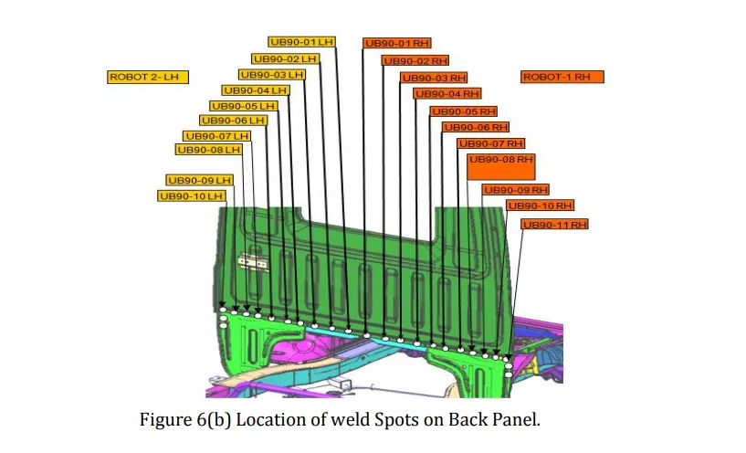
FIG . Location of weld spots and back panel.
* Spot plan clears us that how much robots are to be used and the sequence of the spot will be decided along with which robot will be cover certain spot places.
* Also cycle time should be considered while preparing concept design.
8. CUSTOMER APPROVAL:
* It is also known as design approval process (DAP).
* After design concepts the customer will review the design concepts.
* If the design need to be made simple or some other correction needs to be done in concept design will be discussed and after meeting the requirement of customer, they will give approval to the design to go on with furthur activities.
9. DETAILING & DRAWING RELEASE:
* Once the customer approved the process, the detailing of the fixture parts which is to be manufactured has been done with giving appropriate dimensions and GD&T symbols.
* All the dimensions which is necessary for manufacturing should be included with GD&T in the drawings before releasing the drawing to the manufacturing team.
10. MANUFACTURING / BOP ORDERING:
* The mechanical & electrical parts like sensors, cylinders, etc., which needs for fixture are ordered as per design specifications.
11. MECHANICAL / ELECTRICAL:
* After the materials ordered received to our end. The quality will check the working conditions and technical specs, which meets our requirement.
* After the quality check the mechanical & the electrical parts are assembled as per design.`
12. QUALITY INSPECTION:
* After the assembly again the quality check is done.
* In this all dimensions, positional accuracy, coordinates are checked using CMM.
13. INTERNAL TRIAL:
* After QC check internal trials are made to check the operation of the fixure.
* It is a first trial taken inhouse, so we will see by putting the assembly in the fixture whether the seating of assembly/panel suited correctly, whether the clamping operation are done properly, also whether the pins are getting into the holes,etc,.
14. ONLINE TRIAL:
* The trial will done in automatic made through control panel.
* The process sequence of operations is checked as by the designed way.
15. PACKAGING:
* To avoid damage occur in fixtures while transportation which may also leads to affect the aesthetic look & proper function of fixture packaging has been done.
* After the trials taken have to get the QC confirmation whether the panels met the standards/specs given by customer also whether the fixture meets the customer standards.
16. DISPATCH:
* After the fixture has been packed for delivery as per standards.
* Its been dispatched to the customer.
17. INSTALLATION AS PER LAYOUT:
* As we discussed in design concept preparation, the design of the layout are been prepared at very initial level which gives the information of placements of robots and fixtures.
* According to the design the installation & commissioning team will install the fixtures.
18. TRAILS & TRAINING AT CUSTOMER:
* Production trails will be taken at customer end.
* During technical offer we will be confirmed that n-number of assemblies will be produced within 8hrs/12hrs shifts.
* So,in customer trial we have to achieve the confirmed quantity of assemblies.
* Once it is achieved, training will be given to the operator, staffs, engineers who involved in this process.
* The sequence of working process by the fixture will be explained in detail.
* The check points which has to be done after placing the panels into the fixture will be made clear to them.
19. BUYOFF MEETING:
* After trials and training at customer end, buyoff meeting will be held.
* In this meeting customer will give reviews about the fixtures, sometimes customer may need/feels better to do some addition work also. It will be discussed and finalize in the meeting.
20. FINAL HANDOVER:
* The fixture and the documents supports the fixtures/production will be haded over.
* Documents like poka yoke documents, clamp validation document,ergo sheets,BOM, charts will be delivered and handedover to customers.
* Documents will play a vital role in industry, we should always have a proof for our work done. The sequence of quality of work will be seen through the documents.
* Every automobile industries will follow some standards to maintain documents as per ISO,IATF.
* Now every automobile industries/vendors/suppliers are maintaining the documents as per IATF (International Automotive Task Force).
* IAFT - The International automotive task force is a group of automotive manufactures which aims at providing improved quality products to automotive customers worldwide.
Hence, the process of project execution activities are detailed above.
2)What are the types of joining processes?
There are many joining processes used in BIW like welding, gluing.
The durability and performance of any structure is largely depends on quality & design of components joints. Whole structure can’t be made in one piece. Two fundamental option for joining material & components.
- Metallurgical joining
- Mechanical joining.
Metallurgical joining
* Metallurgical joining includes fusion welding, pressure welding and brazing/soldering which use different energies.There are also methods of chemical joining that use adhesives.
* Different types of metallurgical joining are described below
(A) Welding
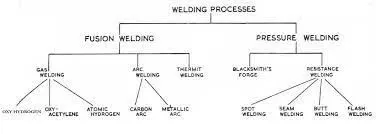
* Welding is a joining process for metals wherein the work pieces to be joined as well as the welding or filler material used experience some melting. A common method for welding, known as arc welding, consists of generating an electric arc between an electrode (which contains the welding or filler material) and the work pieces to be welded together.The arc generates enough heat to melt the electrode and the areas of the work pieces were the welding is performed.
* As the electrode passes over a region while the arc is present, molten metal from the electrode and molten base metal from the work pieces all get mixed together, solidifying to form a strong joint upon cooldown.The electrode contains some flux material, the purpose of which is to stabilize the arc formed by generating gases (carbon dioxide, carbon monoxide, water vapor) that shield the arc from the surrounding atmosphere.
B) Brazing
* Brazing is a process for joining two work pieces together with a filler metal that is sandwiched between them, wherein only this filler metal undergoes melting, i.e., the work pieces do not experience any melting.
* The temperature at which brazing is done must therefore be high enough to melt the filler material, but not the work pieces. Materials used as fillers for brazing are those that melt above 450 deg C. Flux is also used during brazing for the purpose of eliminating oxide films from the surfaces of the work pieces and preventing oxidation.
Soldering
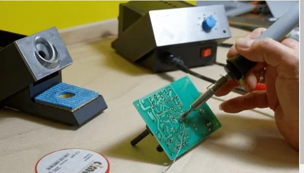
* Soldering is a joining process that's similar to brazing, except that it is performed at much lower temperatures than brazing. Thus, soldering is also a process of joining two work pieces together with a filler metal, such that only this filler metal undergoes melting, i.e., the work pieces do not experience any melting.
* Brazing materials are those that melt above 450 deg C, so soldering materials would be those that melt at less than 450 deg C. 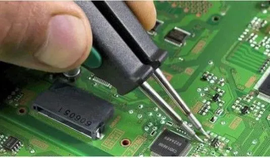
Adhesive Bonding
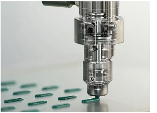
Adhesive Bonding is a process for joining parts using bonding chemicals or materials known as adhesives. It is employed to join polymers and polymer-matrix composites, as well as polymers to metals, metals to metals, and ceramics to metals. Adhesive-bonded joints can withstand shear, tensile, and compressive stresses, but they do not exhibit good resistance against peeling. To overcome the weakness of adhesive bonding against peeling, joints mated together by adhesives must have a good design, i.e., the adhesion area is maximized and mechanical interlocking is employed.
Diffusion Bonding
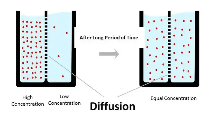
This process works on basic principle of diffusion. Diffusion means movement of molecules or atoms from high concentration region to low concentration region. This is fundamental principle of diffusion welding. In this welding process both the welding plates are placed one over other in high pressure and temperature for a long period of time. This high pressure force starts diffusion between interface surfaces. This diffusion can be accelerated by the application of high temperature. This temperature does not melt the welding plates. The temperature range is about 50-60% of melting temperature. This whole process takes place in vacuum or in inert environment which protects the welding plates form oxidation.
Mechanical joining
Mechanical joining includes bolting, riveting, caulking, shrink fitting, and folding, all of which join workpieces by using mechanical energy.
spot welding
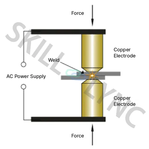
Also called Resistance Spot Welding, spot welding continues to be the main choice of joining processes in the body shop ( it constitutes close to 40% of all joining processes).
* It is a solid-state welding method and is used for joining overlapping sheet metals in projects where strength and durability are not pressing.
* Workpieces are held together under the force exerted by electrodes.
* Typically, the sheets are of the order the 0.3 to 6 mm thickness.
* The process uses two shaped copper alloy electrodes to concentrate welding current into a small "spot" and to simultaneously clamp the sheets. This forces the large current through the spot, which will melt the metal and form the weld.
* Spot welding has fewer applications and tends to harden and warp workpiece materials.
* Low-carbon steel is the most suitable material for spot welding.
3)What is Resistance Welding & its application in the automotive sector?
* Resistance welding is the joining of metals by applying pressure and passing current for a length of time through the metal area which is to be joined. The key advantage of resistance welding is that no other materials are needed to create the bond, which makes this process extremely cost effective.
spot welding
Also called Resistance Spot Welding, spot welding continues to be the main choice of joining processes in the body shop ( it constitutes close to 40% of all joining processes).
* It is a solid-state welding method and is used for joining overlapping sheet metals in projects where strength and durability are not pressing.
* Workpieces are held together under the force exerted by electrodes.
* Typically, the sheets are of the order the 0.3 to 6 mm thickness.
* The process uses two shaped copper alloy electrodes to concentrate welding current into a small "spot" and to simultaneously clamp the sheets. This forces the large current through the spot, which will melt the metal and form the weld.
* Spot welding has fewer applications and tends to harden and warp workpiece materials.
* Low-carbon steel is the most suitable material for spot welding.
Advantage:
* Time - saving compared to TIG or MIG weiding.
* Very suitable for high volume & automated production.
* It does not require grinding after welding (to remove slag formation).
* Minimal material distortion.
* Non-consumable electrode, unlike MIG Welding.
* No slag formation after welding.
Seam Welding :
* Seam welding is similar in principle to spot welding and uses rotating wheel electrodes which roll the overlapping components between them. The welding current passes intermittently through the electrodes, forming a series of welds that overlap one another.
* The seam welding is a types of resistance welding, in which weld is produced by roller electrodes instead of tipped electrodes. Most seam welding processes produce a continuous or intermittent seam weld near the edge of two overlapped metals by using two machine driven roller electrodes.
* Widely used for joining aircraft tanks, refrigerators and oil transformers, this process can be used for welding stainless steel, nickel alloys, and magnesium alloys.
Advantage :
* Seam welds generally have better external appearance due to the absence of indentations. Joints are forged due to pressure and heat applied forming a durable weld. Tools produced through seam welding have excellent mechanical properties. Seam welds join a large surface area thus making strong welds
In this article, we will discuss the first type that is fusion welding.
Opposite to fusion welding, no melting of material is done in solid-state welding and cold welding.
Unlike pressure or solid-state welding, no external pressure is required in the fusion welding process.
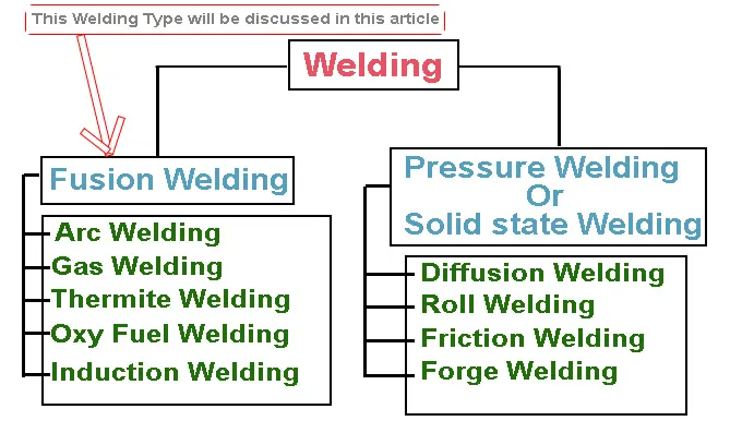
Steps involved in Fusion Welding:
* At first, the parts to be welded are held in position and the molten metal is supplied to the joint.
* The molten metal used to weld the two parts may come from the parent metals or a filler metal which may or may not have the composition of parent metal.
* The joint surface becomes molten because of the heat from the molten filler or other source based on the type of fusion welding used.
* After that, when the molten metal solidifies or fuses, the joint is formed and the fusion welding process is completed.
Types Of Fusion Welding:
* Arc Welding
* Gas Welding
* Thermite Welding
* Oxy Fuel Welding
* Induction Welding
1.Arc Welding:
* Arc welding refers to the group of welding processes in which the metals are heated to melting points by an electrical arc.
* In some arc welding processes pressure is also applied to the workpiece for better weld strength and quality.
* Most of the arc welding process makes use of filler material.
Arc Welding is further classified into the following types:
i) Shielded Metal Arc Welding (SMAW)
ii) Gas Metal Arc Welding (GMAW)
iii) Gas Tungsten Arc Welding (GTAW)
iv) Submerged Arc Welding (SAW)
v) Flux Cored Arc Welding (FCAW)
vi) Plasma Arc Welding (PAW)
vii) Carbon Arc Welding.
2.Gas Welding:
* Gas welding is a welding process in which a strong high-temperature flame is used to weld two metal parts. The high-temperature flame is generated with help of flammable gases.
* The flame is used to generate heat and raise the temperature of the metal piece at the place where the joint is to be made.
* Due to the heat from the gas flame, the metal at the joints starts to melt. The molten metal is joined to another metal workpiece.
* A filler material is also added to the molten metal to act as a binder. The molten joint is allowed to cool and solidify.
* Many different combinations of gases are used to obtain a heating flame. The most common is oxygen-acetylene flame.
3.Thermite Welding:
* Thermite welding is a welding process in which a thermite compound is used to weld two metals together. Thermite is a type of chemical composition of a metal powder. Powder normally consists of a metal and a metal oxide. When this powder is ignited, it undergoes an extremely exothermic redox reaction. Here oxide from one metal transfers to the other metal.
* In this welding process, a huge amount of heat is generated for a brief period. The most common use of thermite welding is to join rail tracks in railways.
* This process does not require any heavy machinery and is very fast.
* This process is also used to repair rail tracks as the molten metal from the reaction can be used to repair the tracks.
4.Oxy-Fuel Welding:
* It is the type of welding process in which oxygen is used as fuel to produce a flame that heats and joins two metal surfaces. This process is also known as oxy-acetylene welding.
* This welding process uses a combination of oxygen and a flammable gas mostly acetylene to create a hot flame to join objects.
* Oxygen and fuel are mixed in the right proportion within a handheld torch or blowpipe to produce a hot flame with a temperature of about 3200 degrees Celcius.
* As steel melts at 1500 degree Celcius, this is the only welding process which can produce such high temperature by combining oxygen and acetylene to melt steel. So steel can be welded using this welding process only. While other non-ferrous metals with low melting points can be welded by using a mixture of oxygen and gases like hydrogen, propane, or coal gas in the oxyfuel welding process.
5.Induction Welding:
* In this type of welding process, electromagnetic induction is used to heat the metal surfaces which are to be joined. An induction coil is present in the welding apparatus which is energized with a radio-frequency electric current. This welding process is mainly used to weld materials that are either electrically conductive or are ferromagnetic materials.
* Electrical insulators and non-magnetic materials can also be welded using this process by implanting them with ferromagnetic or metallic compounds called susceptors.
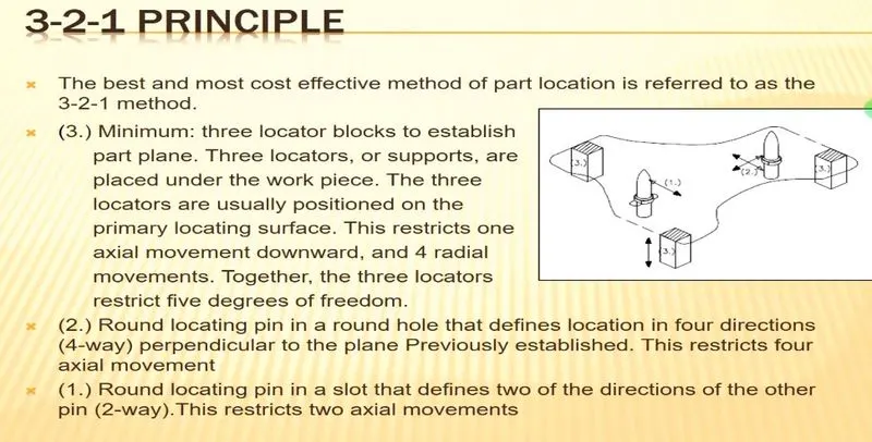
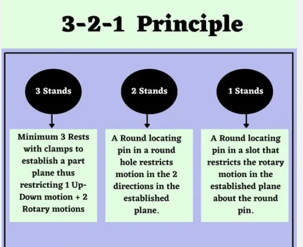
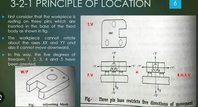
5)What is the 3-2-1 principle?
6)Define Body coordinate system?
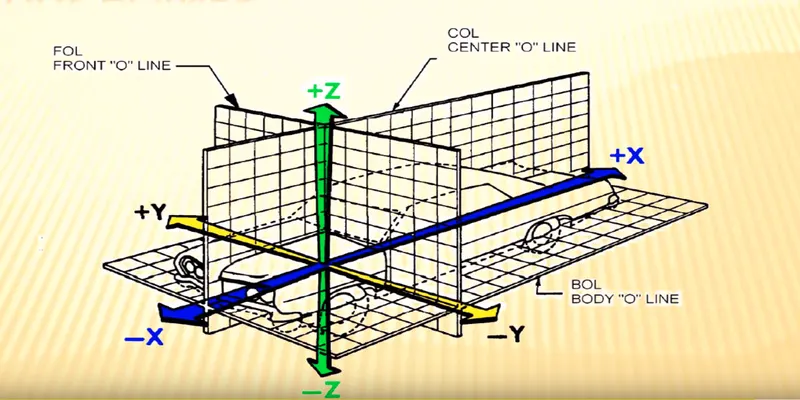
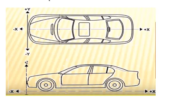
* The orientation of the body coordinate axes is fixed in the shape of body. The x-axis points through the nose of the craft. The y-axis points to the right of the x-axis (facing in the pilot's direction of view), perpendicular to the x-axis.
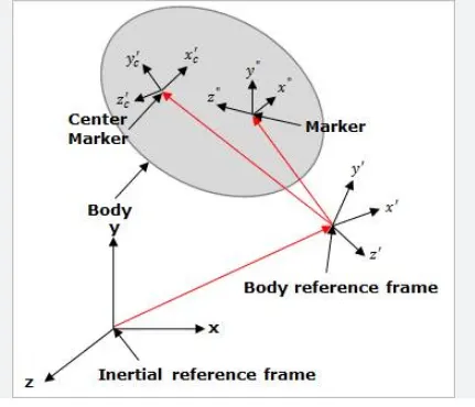
* Coordinate system is a reference system Consisting of a set of point, Lines & surfaces used to define position of point in space either in 2 or 3 dimensions.
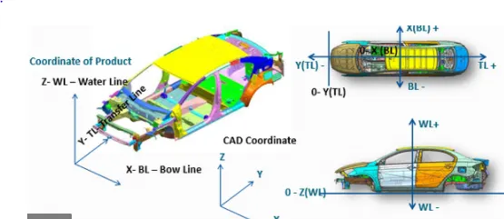
In general BCS is also called as car line or Body line
* Car lines are the (Grid lines) shown on the fixture, which virtually represent the same location in the BIW. All the car line on fixture display the coordinate at corner for reference. With these lines one can easily relate the, location in BIW.
* Some times single coordinate hole is given in the fixture, that also represent the car line coordinates, from that reference point fixture is made and can be inspected. Body coordinate are mentioned near the hole.
Maintaining X,Y & Z co-ordinates in fixture is a very important factor.
* We should try that the co-ordinates of locating and clamping points should not be in three decimal (e.g. X=100.124, Y=245.127, Z=450.458).
* They should be in the whole nos. or max upto 1 decimal . Once these co-ordinates are maintained automatically the BIW base structure is maintained.
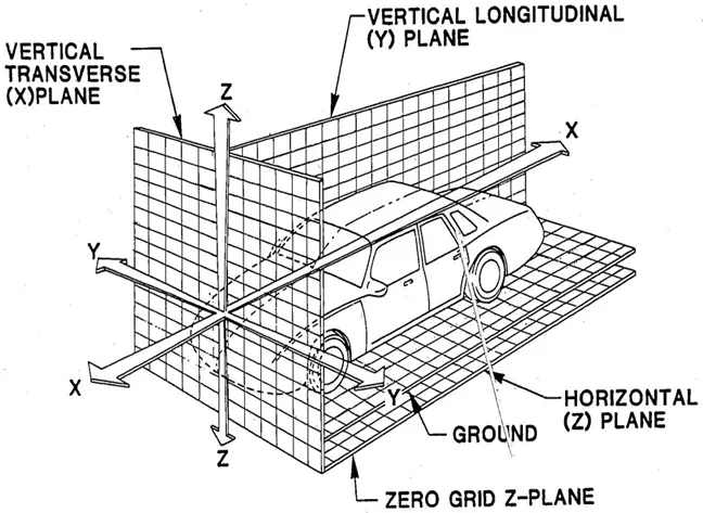
All vehicle product drawings are identified numerically relative to three vehicle planes Description shown below.
1. ( X ) It is in width of BIW – 0 X - is Body Center Line
2. ( Y ) It is in length of BIW – 0 Y is Near Front Bumper
3. ( Z ) It is in Height of BIW - 0 Z is about Center of Wheel
7)Elaborate Body plane system & its essentials?
* Body planes are three mutually perpendicular imaginary planes. These are reference planes in automotive car. These are used to define GD & T of all parts in automotive domain. The measurement from body plane to parts are called body plane dimensions.
* Body planes are essential for because
Use of body plane
* used for define exact position of each part of the car.
* used for quality inspection
* used for making a standard system
* used for assembly of the car
* used for locating all the parts