Week 2:- BiW Fixture Basics Challenge
1. What is the process of project execution activity?
This type of welding is very much used in BIW assemblies most common. The weld is made by conducting strong current through the metal combination to heat up & finally melt the metals at localized points predetermined by design of the electrodes or the work piece to be welded.
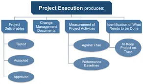
The Project Management Lifecycle involves 4 stages: 1) initiation; 2) planning; 3) execution; 4) closure. The execution phase of the project lifecycle is when the work gets done. Task owners begin work and the project manager oversees that those tasks are completed in a timely manner, while workflow continues smoothly. Project monitoring and control are a significant part of this phase, as issues will always arise and require quick adjustments as the project progresses.
Project Execution Steps
The steps during project execution will change depending on the specific requirements of the project. Those particular steps are typically laid out in the project execution plan. However, there are general activities that should apply to all projects.
Project Execution Phase Activities include:
- Begin work
- Manage workflow for all project tasks
- Issue management
- Risk management
- Manage change orders
- Manage project communications with all stakeholders
- Verify when milestones are reached
- Conduct gateway reviews as required
- Report on project status regularly to stakeholders
The Importance of the Right Software
Most of today’s project tools are focused on project scheduling, which is before the project starts, or project accounting, which is mostly after the project ends (at least periodically). There are very few project execution systems. Ironically, this phase is arguably the most important, as it is when the work actually gets done, taking up the largest amount of time in the project life cycle and is when the most issues occur that set the project off track.
Today, most project execution activities listed above are managed offline, in spreadsheets, word documents and emails. What if there were a system to manage all of that?
Project execution software, or a project execution system is a transactional business system that provides a framework to manage the work of a project. Such a system seamlessly integrates the operations and finances of a project, as they are interrelated when executing a project. The execution of a project must be managed from a task and activities perspective as well as the revenue, cash flow, and margins.
Project Business Automation (PBA) is one such system. PBA connects and automates all your project business processes in one platform. Focused on the business execution side of your project-based company, PBA creates a framework for success that lowers risk, controls costs, and improves deliverability.
2. What are the types of joining processes?
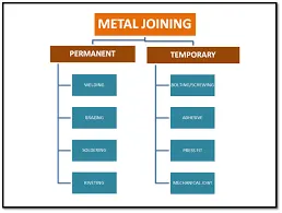
Joining processes are characterized by their ability to fuse or “join” two or more components for the purpose of creating a different object, such as a ready-to-sell consumer product. Most materials can be joined — and there are typically multiple ways to join them. Two-by-fours, for instance, can be nailed or bolted together, whereas sheet metal can be welded or soldered together.
All joining processes involve joining two or more components, and most joining processes require the use of a separate tool or tools. With the help of a tool, such as a nailgun, the components are joined.
Common types of joining processes used in the manufacturing industry include the following:
- Welding
- Brazing
- Soldering
- Bonding
- Nailing
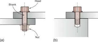
- Screwing
- Bolting
- Riveting
- Clinching
- Stapling
- Press fitting
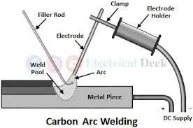
Arc welding is a welding process that is used to join metal to metal by using electricity to create enough heat to melt metal, and the melted metals, when cool, result in a binding of the metals.
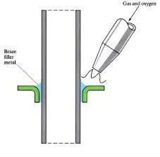
Brazing is a metal-joining process in which two or more metal items are joined together by melting and flowing a filler metal into the joint, with the filler metal having a lower melting point than the adjoining metal. Brazing differs from welding in that it does not involve melting the work pieces.
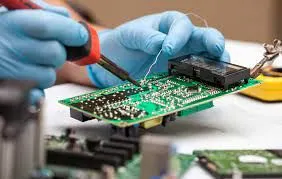
Soldering is a process of joining two metal surfaces together using a filler metal called solder. The soldering process involves heating the surfaces to be joined and melting the solder, which is then allowed to cool and solidify, creating a strong and durable joint.
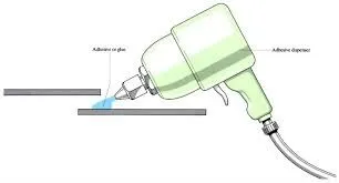
Adhesive Bonding is the process of joining two surfaces together, usually with the creation of a smooth bond. This may involve the use of glue, epoxy, or one of a wide range of plastic agents which bond either through the evaporation of a solvent or through curing via heat, time, or pressure.
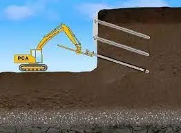
The process starts on drilling the soil and locating the nail and steel bar target points. And drilling is completed the nails must be inserted on holes. Then, the grout is applied into the soil to develop a structural member. Then reinforcement is placed on a soil surface to protect the soil.
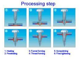
Screws are widely used for parts joining in industry. The definition of effective monitoring strategies for screwing processes can help to prevent or significantly reduce ineffective procedures, defective screwing and downtime.
Bolting is a process that sometimes induces flowering stems in horticultural or agricultural crops before they are harvested, this helps in increased reproduction. Under stress conditions, bolting occurs as an effort to grow seeds, it is also referred to as the survival mechanism of a plant.
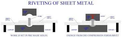
Riveting is a semi-permanent and non-thermal joining method that involves using a mechanical fastener/rivet (a metallic part with a dome-shaped head) to join sheet metal parts. Riveting involves drilling a hole in the two sheet metal parts you want to join together and installing a rivet.
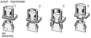
The clinching process is a method of assembling sheet metal without welding or fasteners. With this joining technique, metal parts are deformed locally without the use of any consumables.
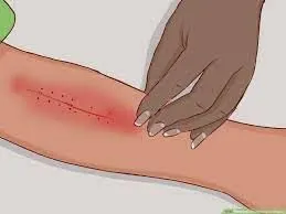
Surgical staples are used to close incisions after surgery. Staples may be a better option in some cases than stitches or sutures. Unlike stitches, surgical staples don't dissolve as your incision or wound heals.
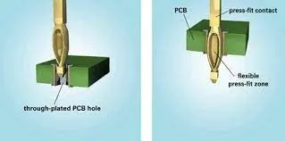
In engineering terms, a press fit— also known as an interference fit— is the fastening of two parts that is achieved by normal force, friction and cold welding. This happens when a shaft is inserted tightly into a slightly smaller hole in another part, with the interference holding both parts in place.
3. What is Resistance Welding & its application in the automotive sector?
Resistance welding is generally used to join two plain metal work pieces together. An electric current is delivered to the metal sheets (or any work pieces being joined) through weld electrodes which apply force to the sheets. This force is then converted to heat. Resistance Spot Welding (often just called spot welding) is a cost-effective joining technology that continues to be very popular in the automotive industry where high reproducibility and automation are essential criteria. The heat is generated so that it melts the metal at the point where they join – the point of ‘resistance’ between the faying surfaces. The electrode then extracts heat from the molten weld area which forms a weld nugget at the point where it solidifies. A force is applied before, during and after a current is applied, which confines the contact area.
Types of Resistance Welding
There are many resistance welding processes with different uses, such as spot welding, seam welding, and butt welding. Each one has a different specific welding application that makes it optimal for a particular situation.
1. Resistance Spot Welding
Resistance spot welding has been used extensively in the automotive industry for the joining of steel and in the aerospace industry for airframe components made from aluminium alloys. It is one of the oldest and simplest forms of resistance welding, in which a weld nugget is produced by passing an electric current between the two metal components whilst they are held together between electrodes, typically made from copper-based alloys due to its superior conductive properties.
2. Resistance Seam Welding
Resistance seam welding is a variation of the standard spot welding form, however instead of spot one nugget, a series of overlapping nuggets is produced. This is usually done by replacing the conventional spot welding electrodes with wheels, which turn as the parts are fed between them. The process thus produces a continuous welded seam rather than a single spot. Seam welding is often used in the production of thin sheet, leak-tight containers such as fuel tanks, and is generally unsuitable for welding aluminium.
3. Resistance Projection Welding
Resistance projection welding is a form of resistance welding where the electricity, force, and weld time are concentrated on raised ‘projections’ across the surface. Projection welding is generally used for welds using thicker materials than the thinner metal pieces that spot welding is usually required for, and often not metals. It is used primarily in the electrical, automotive and construction industries.
4. Resistance Butt Welding
Resistance butt welding is a process in which the two components of similar cross section can be joined together in one operation that takes place simultaneously across the entirety of the affected object, rather than just in small spots. The welding application of butt welding is often in wires and rods with small diameter measurements, generally up to about 16mm diameter.
5. Flash Butt Welding
Flash butt welding is similar, but in this case the energy transfer is primarily provided by the resistance heat arising from the parts themselves. This is a faster type of resistance welding where the welder joins the parts by applying some pressure, then by passing a heavy current through the joint which burns away surface irregularities. After the weld has generated enough heat, the parts are connected by applying heat and pressure simultaneously. This produces a forge butt weld with no melted metal remaining in the joint.
Advantages
- Similar and dissimilar metals are capable of being welded
- Highly automated
- Efficient with high production rate and high welding rate
- Cost-effective
- Environment-friendly, produces little waste or pollution
- No need for filler metal or extraneous materials such as rods, fluxes, inert gasses, oxygen, or acetylene are required
Disadvantages
- Complex and often high-cost machinery – a resistance welding machine generally requires a high level of technically trained personnel to use
- The thickness of the work piece is often limited
- It is less efficient for high conductive materials
- High electric power required
Applications of Resistance Welding
Resistance welding is mainly used in the mass production of welding sheet metal, wires and tubes, etc.
Resistance is used for making cutting tools.
Resistance welding is used in welding of aircraft and automobile parts.
Resistance welding is used for welding process in making fuel tanks of cars, trucks, tractors, etc.
Projection welding (a types of resistance welding) is widely used in the production of nuts and bolts.
4. What is fusion welding & types of fusion welding with its application in the automotive sector?
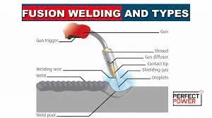
Fusion welding is a process that uses heat to join or fuse two or more materials by heating them to melting point. The process may or may not require the use a filler material.It is a generic term for welding processes that rely on melting to join materials of similar compositions and melting points. Due to the high-temperature phase transitions inherent to these processes, a heat-affected zone is created in the material.
Electrical
Arc
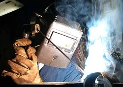
Arc welding is one of the many types of fusion welding. Arc welding joins two pieces of metal together by using an intermediate filler metal. The way this works is by completing an electrical circuit to create an electrical arc. This electrical arc is 6500 °F (3593 °C) in its center.[3] This electrical arc is created at the tip of the filler metal. As the arc melts the metal, it is moved either by a person or a machine along the gap in the metals, creating a bond. This method is very common as it is typically done with a hand held machine. Arc welding machines are portable and can be brought onto job sites and hard to reach areas. It is also the most common method of underwater welding. Electrical arcs form between points separated by a gas. In the process of underwater welding a bubble of gas is blown around the area being welded so that an electrical arc may form. Underwater welding has many applications. Ship hulls are repaired and oil rigs are maintained with underwater arc welding.
Resistance welding is done using two electrodes. Each comes into contact with one of the pieces being welded. The two pieces of metal are then pressed together between the electrodes and an electric current is run through them. The pieces of metal begin to heat up at the point where they come into contact. The current is passed through the metal until it is hot enough that the two pieces melt and conjoin. As the metal cools the bond is solidified. This process requires large amounts of electricity. In most cases transformers are needed to provide enough amps. Resistance welding is a very prevalent form of fusion welding. It is used in the manufacturing of automobiles and construction equipment.
Laser beam
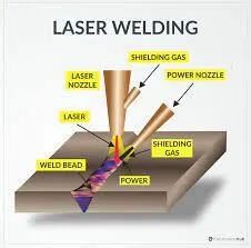
Conduction welding, also known as laser beam welding or radiation welding, is a highly precise form of fusion welding. "Laser" is an acronym for Light Amplification by Stimulated Emission of Radiation. The laser emits light in bursts called pumps.These bursts are aimed at the seam of the metals desired to be conjoined. As the laser bursts it is guided along the seam. These intense bursts melt the metal. The two metals when melted mix with each other. Once it has cooled the seam created is a strong bond. Lasers are efficient because they can be configured to make multiple welds at once. The laser beam can be split and sent to multiple locations greatly reducing the cost and amount of energy required. Laser beam welding finds applications in the automotive industry.
Induction
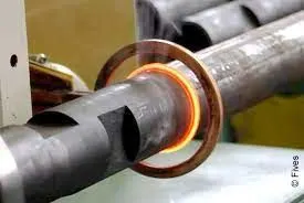
Induction welding is a form of resistance welding. However, there are no points of contact between the metal being welding and the electrical source or the welder. In induction welding a coil is wrapped around a cylinder. This coil causes a magnetic field across the surface of the metal inside. This magnetic field flows in the opposite direction of the magnetic field on the inside of the cylinder. These magnetic flows impede each other.[6] This heats the metal and causes the edges to melt together.
Chemical
Oxyfuel
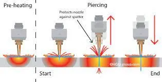
Flame contact is a very common form of welding. The most popular kind of flame contact welding is oxyfuel gas welding. Flame contact welding uses a flame exposed to the surface of the metals being welded to melt and then join them together. Oxyfuel uses oxygen as a primary ignition source in tandem with another gas such as acetylene to produce a flame which is 2500 °C at the tip and 2800-3500 °C at the tip of the inner cone.[7] Other gasses such as propane and methanol can be used for oxyfuel welding. Acetylene is the most common gas used in oxyfuel welding.
Solid reactant
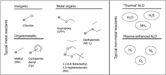
Solid reactant welding uses reactions between elements and compounds. Certain compounds when mixed create an exothermic chemical reaction, meaning they give off heat. A very common reaction uses thermite, a combination of a metal oxide (rust) and aluminum. This reaction produces heat over 4000 °F.[7] Solid reactant compounds are channeled to the two pieces of metal being joined. Once in place, a catalyst is used to start the reaction. This catalyst can be a chemical or another heat source. The heat created melts the metals being joined. Once it cools, a bond is formed. From welding together train tracks to entering bank vaults, solid reactant welding has many niche uses.
APPLICATION
Fusion welding has been a critical factor in the creation of modern civilization due to its vital role in construction practices. Besides bolts and rivets, there are no other practical methods for joining pieces of metal securely. Fusion welding is used in the manufacture of many everyday items, including airplanes, cars, and structures. Beyond construction, a large community uses both arc and flame contact welding to create artwork.
5. What is the 3-2-1 principle?
A fundamental concern in metalworking is locating the part to be machined, punched, bent, or stamped relative to the work platform (fixture). For example, a CNC machine tool starts its process at a specific point relative to the fixture and proceeds from there. Hence, the accuracy with which a part is machined is quite dependent on the accuracy with which it is positioned in the fixture.
Accurate locating of not just one part, but each and every part that is loaded into the fixture is crucial. Any variation in part location on the fixture adds to the dimensional tolerance that must be assigned to the finished parts.
Additionally, the method of supporting and securing the part in the fixture affects not only dimensional tolerances, but surface finishes as well. This is true because improper supporting or clamping can temporarily or permanently deform the part. Hence, techniques for supporting and clamping must be considered together with the method of locating in order to assure repeatability from part-to-part.
Locating of a part to be machined is a three-step process:
1. Supporting
2. Locating (positioning)
3. Holding (clamping)
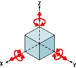
The Locating Process: Degrees of Freedom
In order to completely specify the position in space of a three-dimensional
object (such as the cube that’s shown), we refer to six coordinates:
- Translational position along the X-axis
- Translational position along the Y-axis
- Translational position along the Z-axis
- Rotational position about the X-axis
- Rotational position about the Y-axis
- Rotational position about the Z-axis
These six coordinates are known as the six degrees of freedom of a three-dimensional object. As the double-headed arrows indicate, the translational and rotational positions can vary in either direction with respect to each of the three axes.
To completely prevent movement, all six degrees of freedom must be restricted.
The Locating Process: 3-2-1 Method
We have two objectives when mounting a part in a fixture for machining:
1. Accurately position the part at the desired coordinates.
2. Restrict all six degrees of freedom so that the part cannot move.
A widely used method of accomplishing these two objectives uses the 3-2-1 principle, so-called because it entails three steps that employ three, then two, then one fixed points of known location. Since that adds up to six fixed points, it’s also known as the six point method.
In the three steps of the 3-2-1 method, three mutually perpendicular planes, called datum planes, are introduced, one at each step. These three planes define the workpiece position, and together with opposing clamping forces fully constrain the part. Let’s take a look at the details of the 3-2-1 method.
First Plane
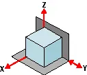
Geometry tells us that three points are required to define a plane. This is the "3" in 3-2-1. So, three specific points are used to define the first plane. Fewer than three points cannot define a plane, and in the real world dimensional tolerances mean that four or more points will not be coplanar. A real-world, less than ideally perfect part placed on four or more reference points will, in fact, rest on only three of the points due to its less than perfect surface. Different parts may rest on different combinations of three points, resulting in variation between finished parts. A stool can be used to illustrate this concept. A two-legged stool would certainly be unstable. A three-legged stool sits rock-solid. A four-legged stool is often found to rock. In the illustration, a three dimensional part, represented by a cube, is placed on a datum plane defined by three support points. The part’s six degrees of freedom have now been reduced to three. It can still move along the X or Y axes, and it can still be rotated about the Z axis. (The part cannot move along the Z axis because it is held against the plane by clamping force.
TIPS
- Use the largest surface of the part for the first ("primary") reference plane.
- Position the three support points as far apart as possible.
- If more than three support points are required to prevent deflection, make the additional points adjustable.
Second Plane
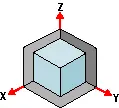
A second plane, if it is perpendicular to the first, can be defined by two points, the "2" in 3-2-1. The part is now constrained to one degree of freedom: movement along the Y axis. (The part cannot move along the X or Z axes because it is held against the planes by clamping force.)
TIPS
- Use the largest surface of the part for the first ("primary") reference plane.
- Position the three support points as far apart as possible.
- If more than three support points are required to prevent deflection, make the additional points adjustable.
Third Plane
A third plane, if it is perpendicular to both of the first two planes, can be defined by one point, the "1" in 3-2-1. The part is now entirely constrained. It cannot move along or rotate about the X, Y, or Z axes. (Remember that the part is held against each of the three planes by clamping force.)
TIPS
- If more than one support point is required to prevent deflection, make the additional points adjustable.
Machined is Best
It’s best if the workpiece surfaces intended to contact the support points are machined. Cast surfaces are usable, but then tend to create tolerance problems. Machined holes are the number one choice. Two machined holes can be used to eliminate all but one degree of freedom.
Repeatability
Repeatability
Repeatability is a paramount concern. It means that each part should be nearly identical to each other part coming off the same fixture. "Nearly identical" actually has a specific, quantifiable meaning: key dimensions of all parts produced on the same fixture must fall within defined tolerances.
In order to stay within tolerances, it’s best if the workpiece surfaces intended to contact the support points are machined. Cast surfaces are usable, but they tend to create tolerance problems. Machined holes are the number one choice, because two machined holes can be used to eliminate all but one degree of freedom.
The next best feature to use for consistent locating is machined surfaces at right angles. The "machined surface" desired here can simply be a tab or small flat specifically included for locating purposes.
Repeatability is achieved through application of the 3-2-1 method to the three aspects of the locating process:
1. Supporting
2. Locating (positioning)
3. Holding
Supporting
- The part is supported from "below" with reference to the Z axis. (Introduction of the first reference plane.)
- Gravity positions the part against the support locator.
- Provide adjustable auxiliary support points as needed to prevent deflection.
- Vertical location with respect to the fixture is now established
- The part is positioned horizontally, in the X-Y plane. (Introduction of the second and third reference planes.)
Holding
- The part is clamped against fixed locators. Therefore, a known and unvarying position of the part is maintained with respect to the X, Y, and Z axes.
- One strap clamp or clamp arm will restrict the workpiece in three dimensions due to friction between the workpiece and clamp. However, friction alone may not be enough to prevent the workpiece from moving during machining.
- Cutting forces will not move a properly supported and clamped part.
Locating
The part is positioned horizontally, in the X-Y plane. (Introduction of the second and third reference planes).
Summary: Clamping Rules of Thumb
- Define three reference planes on the workpiece and fixture.
- Provide one opposing clamping force opposite each plane to restrict movement.
- When in doubt, rely on additional cylinders to take up uncertainty.
6. Define Body coordinate system?
Body Coordinates
The noninertial body coordinate system is fixed in both origin and orientation to the moving craft. The craft is assumed to be rigid.
The orientation of the body coordinate axes is fixed in the shape of body.
The x-axis points through the nose of the craft.
The y-axis points to the right of the x-axis (facing in the pilot's direction of view), perpendicular to the x-axis.
The z-axis points down through the bottom the craft, perpendicular to the xy plane and satisfying the RH rule.
Translational Degrees of Freedom
Translations are defined by moving along these axes by distances x, y, and z from the origin.
Rotational Degrees of Freedom
Rotations are defined by the Euler angles P, Q, R or Φ, Θ, Ψ. They are:
| P or Φ | Roll about the x-axis |
| Q or Θ | Pitch about the y-axis |
| R or Ψ | Yaw about the z-axis |
Unless otherwise specified, by default the software uses ZYX rotation order for Euler angles.
7. Elaborate Body plane system & its essentials
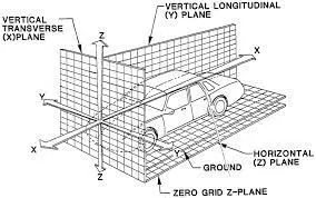
UNDER BODY :
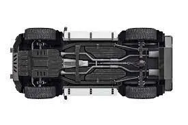
Underbody is the base of BIW, it consists of sub-assembly of the engine room, rear floor, and chassis.
UPPER BODY :
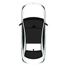
The upper body is the composition of Body Side L/R, Roof Panel, Cowl & Dash, front fender, rear fender, all pillars.
MAIN BODY :
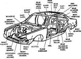
The main body is the assembly of the Under Body and Upper Body.
CLOSURES :
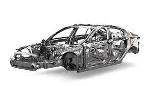
All Doors, Bonnet(Hood), Deck lids are called closures.