Week 2:- BiW Fixture Basics Challenge
1) What is the process of project execution activity?. It starts with basic requirement/RFQ we received from the customer. As shown in the figure there are various steps involved in project activities, They will be explained in detail below.
1.RFQ: Request For Quotation. In this where the customer gives the requirement/specifications in detail for the given projects in the form of data or documents. Also, the customer specifies its technical offer, commercial offer, etc., how the project will be executed & the timeline of the project also will be mentioned.
2.FIRST SPEC. DISCUSSION MEETING:After RFQ received, Technical offer, commercial offer, a timeline of the project, etc., will be discussed and prepared from outside.In this time required for Data study,3D design concept, simulation validation, quality check,2d drawing release, Bought outs, manufacturing, Assembly, installation & commissioning will be discussed and prepared in the technical offer.Based on the technical offer, the commercial offer will be finalized.
3.OFFER SUBMISSION:After the finalization in the meeting, the offers will be submitted to the customer end.Customer will arrange to get an offer from other suppliers too.Based on the Technical, cost, quality, standard and name in the industries, the customer will be finalizing the offer.
4.LOI/PO RECEIPT: After an offer has been finalized customer will be releasing the LOI/PO (Purchase order).Once PO is released we have to start the work. After getting PO from the customer; we have to prepare the schedule.
5.SCHEDULE PREPARATION:Once the PO released from the customer we will be working on Preparation of schedule which should be matched our planned commitment in the technical offer/customer required time. Schedule preparation is nothing but dividing the different activities like Kick off meeting, design data study, DAP, Simulate Quality check.2D detailing, Drawing check, Release of BOM, Manufacturing, Bought outs of electrical & mechanical components, Assembly of the fixture, paint, trial run out, installation and commissioning at customer end etc.
7.DESIGN CONCEPT PREPARATION: Before the design concept, we have to study the data of consumer requirement thoroughly which is carried out in Design data study activities. During the design data study, we will proceed with rough sketches to get a flow while designing concepts. The concept preparation would include the process like load act on panels, clamping process, which spot should be welded first, travel of the gun. In this concept preparation, we should conceptualize the basic data like spot plan, cycle time etc. The weld gun should not collapse while travelling, so by considering this have to make a concept preparation. To avoid collapses of weld gun or robots during travelling, Spot plan will be done at the initial stage.
8.CUSTOMER APPROVAL: It is also known as the Design Approval Process (DAP).After design concepts; the customer will review the design concepts. If the design need to be made simple or some other correction needs to be done in concept design will be discussed and after meeting the requirement of the customer, they will give approval to the design to go on with further activities.
9.DETAILING & DRAWING RELEASE: Once the customer approved the process, the detailing of the fixture parts which is to be manufactured has been done with giving appropriate dimensions and GD&T symbols. All the dimensions which are the necessity for manufacturing should be included with GD&T in the drawings before releasing the drawing to the manufacturing team.
10.MANUFACTURING / BOP ORDERING: The mechanical & electrical parts like sensors, cylinders, etc., which needs for a fixture are ordered as per design specifications.
11.MECHANICAL / ELECTRICAL ASSEMBLY: After the materials ordered received to our end. The quality will check the working conditions and technical specs. This meets our requirement. After the quality check, the mechanical & the electrical parts are assembled as per design.
12.QUALITY INSPECTION: After the assembly again the quality check is done. In all dimensions, positional accuracy, coordinates are checked using CMM.
13.INTERNAL TRIAL:After QC check internal trials are made to check the operation of the fixture. It is a first trial taken in-house, So we will see by putting the assembly in the fixture whether the seating of assembly/panel suited correctly, whether the clamping operation is done properly, also whether the pins are getting into the holes, etc.
14.ONLINE TRIAL: The trail will be done in automatically made through the control panel.The process sequence of operations is checked as by the designed way.
15.PACKAGING: After the trials taken have to get the QC confirmation whether the panels met the standards/specs. Given by the customer also whether the fixture meets the customer standards. After approval of QC, Packaging is been done as per standards. Certain companies follow certain packaging standards, so the packaging should be one as per customer standards.
16.DESPATCH: After the fixture has been packed for delivery as per standards. It’s been dispatched to the customer.
17.INSTALLATION AS PER LAYOUT:As we discussed in design concept preparation, the design of the layout are been prepared at a very initial level which gives the information of placements of robots and fixtures. According to the design the installation & commissioning team will install the fixtures.
18.TRAILS & TRAINING AT CUSTOMER: Production trials will be taken at the customer end. During the technical offer, we will be confirmed that n-number of assemblies will be produced within 8hrs/12hrs shifts. So in customer trial, we have to achieve the confirmed quantity of assemblies. Once it is achieved, training will be given to the operator, staffs, engineers who involved in this process.
19.BUYOFFMEETING: After trials and training at customers end, buyoff meeting will be held.In this meeting customer will give reviews about the fixtures, Sometimes a customer may need/feels better to do some additional work also. It will be discussed and finalize in the meeting.
20. FINAL HANDOVER: The fixture and the documents support the fixtures/production will be handed over. Documents like clamp validation document, ergo sheets, BOMs, Charts will be delivered and handed over to customers. Documents will play a vital role in the industry; we should always have a proof for our work done.
2.What are the types of joining processes?
The durability and performance of any structure is largely dependent on the quality and the design of the component joints.
Two fundamental options for joining materials and components.
1)Mechanical Joining
2)Metallurgical Joining
1)Mechanical Joining-
A)Mechanical Fastening- Mechanical fasteners are most widely used for temporary joints
with the exception of rivets, which need to be broken ordestroyed for dismantling.materials are joined together using fasteners (e.g., screws, nails, nuts, bolts).
Advantages- Any shape or material,can be disassembled,often the least expensive method for volume production.
Disadvantages- Do not develop the full strength of the base material; do not produce hermetic seals, fasteners are extraparts, need to drill holes.
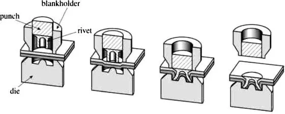
B) Self Piercing Riveting- Although the self-piercing riveting (SPR) process is a young
joining technology, it has become more and more popular during the last decades, especially in the automotive industry. This is a quick, cheap and single-step technique, using a semi-tubular rivet
to fix the sheet components into a mechanical joint.No pre-drilled hole is needed; the rivets are pushed directly into the sheets clamped together between a blank holder and a die in a press tool. The punch, under the pressure conveyed by a hydraulic power device, pushes the rivet to penetrate into the top plate, and the die shape causes the rivet to flare within the lower sheet in order to form a mechanical interlock. The mechanical behaviour of SPR joints strongly depends on the mechanical interlock created within the base materials.
C)Hemming- Hemming or seaming are two similar metal working process in which the sheet metal edge is rolled over on itself.
Hemming - edge roll to itself
Seaming- Two material edges are joined.
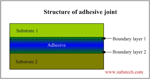
D) Adhesive Bonding- Whilst forming an integral part of a wide variety of fabricated products, adhesives offer the potential to create new, challenging product designs. Structural and speciality
adhesives account for about 30% of total adhesive and sealant sales, with uses in many industries.
2)Metallurgical Joining-
Metallurgical joining includes fusion welding, pressure welding and brazing/soldering which use different energies. Every joining method has advantages and disadvantages.To ensure efficient joining, you need to select the right method according to the materials and joining conditions.
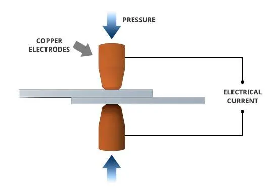
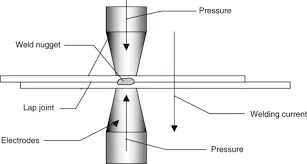
Resistance Welding- Resistance Welding is a welding process, in which work pieces are welded due to a combination of a pressure
applied to them and a localized heat generated by a high electric current flowing through the contact area of the weld.
1)Spot welding.
2)seam welding.
3)Projection welding.
4)Resistance butt welding.
Fusion Welding- Fusion welding processes will be described in this chapter, including gas
welding, arc welding, and high-energy beam welding. The advantages and disadvantages of each process will be discussed.
Types of Fusion Welding
- Arc Welding
- Induction Welding
- Oxyfuel welding
- Laser Welding
- Solid Reactant
Pressure Welding- The joining of tubular (hollow, sectioned) parts to each other or for rods, sheet-like pieces and occasionally for pipe segments, is often achieved by using technology that uses a pressure welding process. These processes use mostly electrical, thermochemical or mechanical energy, and the implementation is butt, stud or projection welding.
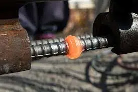
Types Of Pressure Welding
- Diffusion Welding
- Friction Welding
- Ultrasonic Welding
- Cold Pressure Welding
- Forge Welding
- Explosion Welding
Brazing or Soldering-In case of brazing joining of metal pieces is done with the help of filler metal. Filler metal is melted and distributed by capillary action between the faying surfaces of the metallic parts being joined. In this case only filler metal melts. There is no melting of workpiece metal.Soldering is very much similar to brazing and its principle is same as that of brazing. The
major difference lies with the filler metal, the filler metal used in case of soldering
should have the melting temperature lower than 450oC.
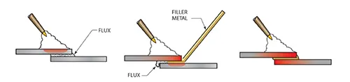
- Torch Brazing
- Induction Brazing
- Resistance Brazing
- Furnance Brazing
- Dip Brazing
3.What is Resistance Welding & its application in the automotive sector?
RESISTANCE WELDING:- Resistance Welding is a welding process, in which work
pieces are welded due to a combination of a pressure applied to them and a localized heat generated by a high electric current flowing through the contact area of theweld.Developed in the early 1900’.
RW does not requiring the following:
1- Consumable electrodes
2- Shield gases
3-Flux
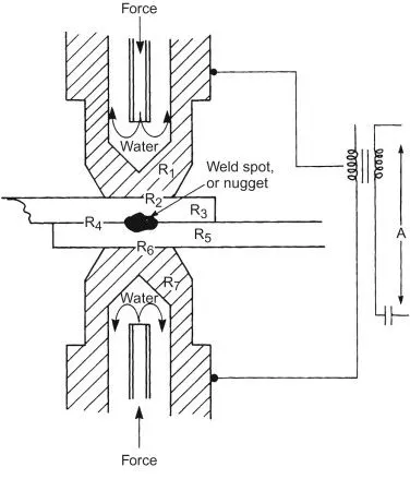
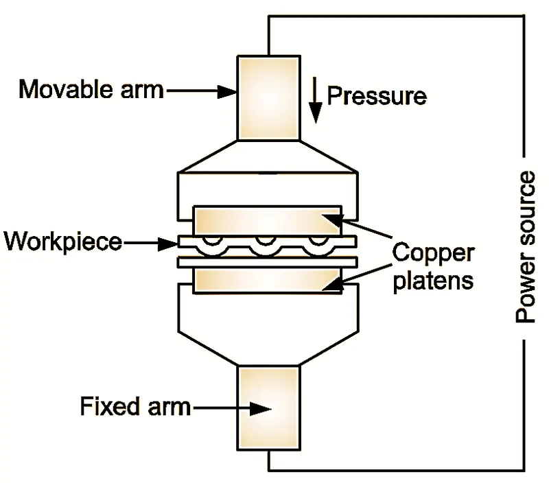
RESISTANCE SPOT WELDING:- Spot weld is probably the most common type of resistance welding. The material to be joined between two electrode,pressure is applied, and the current is on.RSW uses the tips of two opposing solid cylindrical electrodes Pressure is applied to the lap joint until the current is turned off in order to obtain a strong weld.RSW uses the tips of two opposing solid cylindrical electrodes Pressure is applied to the lap joint until the current is turned off in order to obtain a strong weld.
RESISTANCE PROJECTION WELDING:-
It is a resistance welding process for joining metal components or sheets with embossments directly applying opposing forces with electrodes specially designed to fit the shapes of the workpieces The current and the heat generation are localised by the shape of the workpiece either with their natural shape or with specially designed projection .
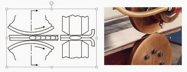
RESITANCE SEAM WELDIND:- Seam Welding is high speed and clean process, which is used when continuous tight weld is required (fuel tanks, drums, domestic radiators).
(a) Seam-Welding Process in which rotating rolls act as electrode.
(b) Overlapping spots in a seam weld.
(c) Roll spot weld.
FLASH BUTT WELDING-
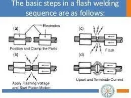
Heat is generated from the arc as the ends as the two members contacts. An axial force is applied at a controlled rate Weld is formed in plastic deformation.
In this two electrode holders are used in which one is fixed and other is movable.
Initially the current is supplied and movable clamp is forced against the fixed clamp due to contact of these two work pieces at high current, flash will be produced.
When the interface surface comes into plastic form, the current is stopped and axial pressure is increased to make joint. In this process weld is formed due to plastic deformation.
4.What is fusion welding & types of fusion welding with its application in the automotive sector?
Fusion-welding processes use heat to melt the base metals. In many fusionwelding operations, a filler metal is added to the molten pool to facilitate the process and providebulk and strength to the welded joint. A fusion-welding operation in which no filler metal is addedis referred to as an autogenous weld.
TYPES OF FUSION WELDING:
- Arc welding
- Laser welding
- Induction Welding
- Oxyfuel welding
- Solid Reactant
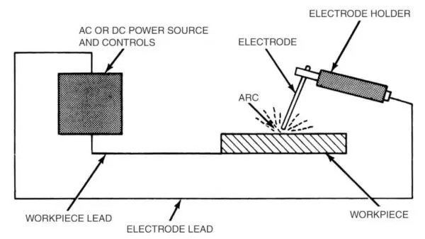
ARC WELDING:- A fusion welding process in which coalescence of the metals is achieved by the heat from an electric arc between an electrode and the work.Electric energy from the arc produces
temperatures ~ 10,000 F (5500 C), hot enough to melt any metal Most AW processes add filler metal to increase volume and strength of weld joint.
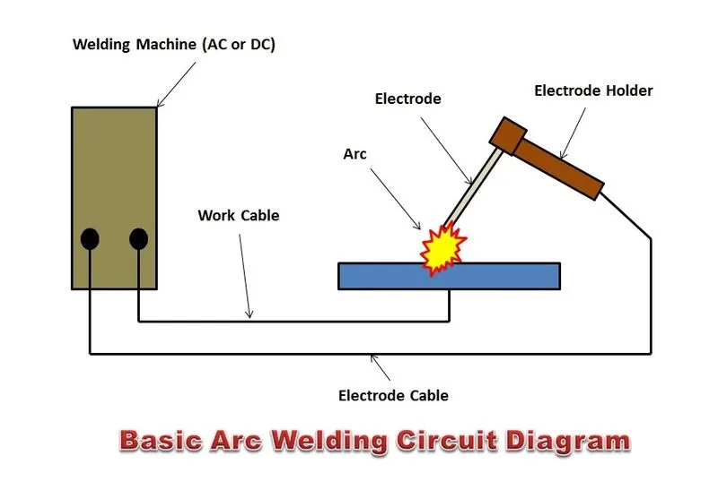
TYPES OF ARC WELDING:
1.MANUAL METAL ARC WELDING:- This is a group of processes in which heat required for fusion is generated by the electric arc formed between a metallic electrode & the base metal. The electrode is consumed in the arc & provides the filler metal for the joint. The electric arc is an ideal source of welding heat. The extremely high arc temperature of over 50000C permits it to supply a large amount heat to a small area. Hence the melting in the base metal is restricted to a narrow zone. Among the arc processes, manual metal arc is the most common, versatile and inexpensive one and account for 60% of the total welding in advanced countries and over 90% of the total
welding in India.
2.GAS SHEILDED METAL ARC WELDING (Metal Inert Gas /MIG welding)- MIG (Metal–Inert-Gas Welding) is also known as GMAW (Gas–Metal-Arc Welding). In this process, coalescence is achieved by an electric arc formed between the work piece and a continuous consumable solid wire electrode, which is fed through a gun at controlled speeds. Inert gas flows through coaxial passage in the gun and forms a blanket over the weld puddle to protect it from atmospheric contamination.The power source is a rectifier or motor generator giving DC.
 .
.
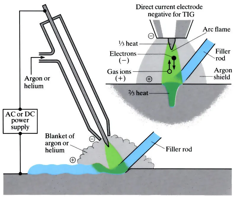
3.GAS SHEILDED TUNGSTEN ARC WELDING(Tungsten Inert Gas /TIG welding)- TIG (Tungsten-Inert-Gas) welding is also termed as GTAW (Gas-Tungsten-Arc Welding). In this process, an arc is struck between a non-consumable tungsten electrode and the base metal. The inert argon or helium or argon-helium mixture shields the arc. A filler wire may or may not be used. When it is used, the welder feeds it externally into the arc in the form of rod or strip. The welder also has to control the arc length and arc travel speed. An AC power source is used for welding aluminum & its alloys, while a DC source is used for other metals. This is an ideal process for welding non-ferrous metals and stainless steels of limited thickness.
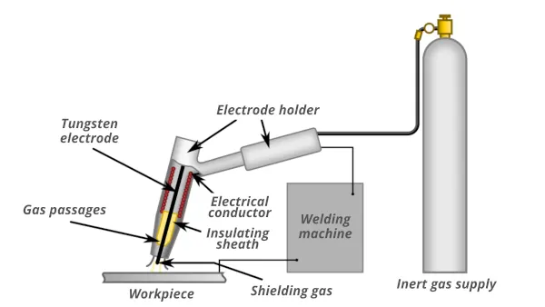
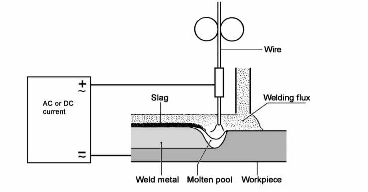
4.SUBMERGEED ARC WELDING- This is mostly used as a fully- automatic process, and sometimes as a semiautomatic process. The electrode is a continuous metallic wire (solid or flux cored) in the form of a spool or a coil. It is fed automatically into the arc at a constant speed. The arc is covered with a layer of dry granular flux fed into the welding groove, which performs the same functions as the coating of a manual electrode. The arc is created between the continuous
wire lowered through the flux and the base plate. The arc remains covered by the flux, hence
the name. As the arcing continues either the welding or the welding head moves, feeding the
flux ahead of flux from a hopper. The arc length is automatically controlled.
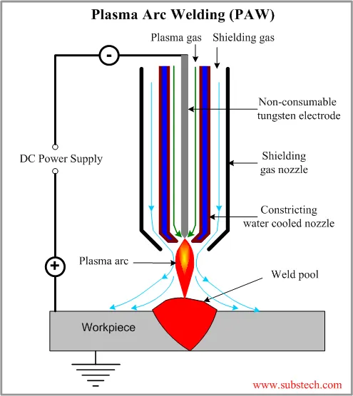
5.PLASMA ARC WELDING- Plasma is considered the fourth state of matter, the other three being solid, liquid, and gas.
Plasma is a gas, which has partially dissociated into positive ions, and negative electrons.
Plasma is formed when an electric discharge takes place in a gas, and also in an electric arc
(the blinding light of an arc comes from the plasma). In normal arc welding processes,
moving gas streams easily blows the plasma away. But in plasma processes which are listed
below, the plasma is contained and used effectively:
Plasma arc welding.
1- Micro-plasma arc welding.
2- Plasma-MIG welding.
3- Plasma arc cutting.
4- Plasma spraying.
LASER WELDING:-
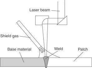
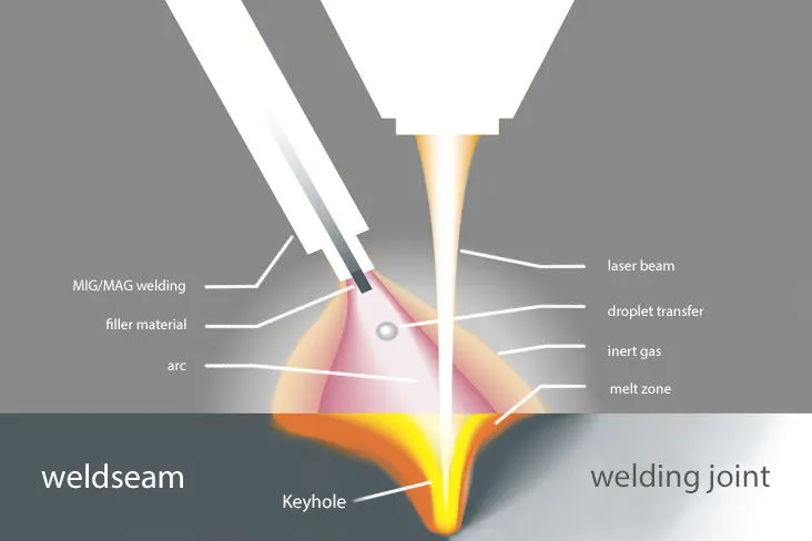
Another type of fusion welding is laser welding. Also known as laser welding, it involves the use of light radiation to produce heat.The laser welding rig essentially blasts the surfaces with radiated light. With each blast, the surfaces become a little hotter. As the objects melt, they fuse together.
INDUCTION WELDING-
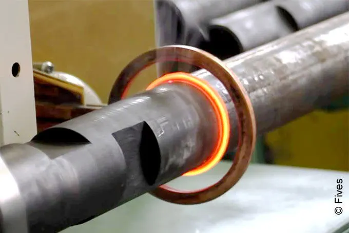
Induction welding for thermoplastic composite materials uses an alternating current flowing through a coil to induce an electromagnetic field and generate eddy current inside laminate with various fiber orientations – the generated heat causes the laminate to heat up and melt the polymer. As a pressure is applied to the induction heating zones, cohesive bonding may occur during the melting of the polymer. The welding quality of the composite materials is highly influenced by the temperature varying inside the heating zones. Thus, it is beneficial for induction welding if temperature varying during heating can be acquired given a set of welding parameters, such as current, pressure, fiber orientations, etc. Conducting practical induction heating experiments for this purpose is laborious and time consuming given the large varying space of welding parameters. In this paper, we propose to address this problem by using machine learning techniques to model the relation between the welding parameters and the temperature varying inside the heating zones. We conduct two sets of induction heating experiments for laminate welding and the collected sample temperature varying data are used to train the neural networks with input of welding parameters and output of the predicted temperature varying.
5.What is the 3-2-1 principle?
One method of reducing manufactring cost per component is to reduce machining cycle time. The manufacturing cycle time can be reduced by reducing nonproductive time like loading, unloading, and the placing of work piece onto the machine. Here jig and fixture design has important role to play. Productive time for a machine is the time required for metal cutting oprtation by the machine.
For a fixture designer, the major portion of design time is spent deciding how to locate the work piece in the fixture.
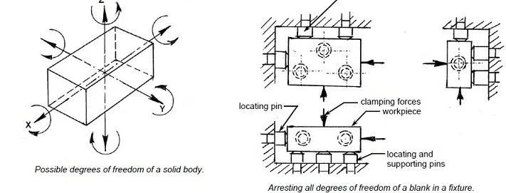
You know that any free body has a total of twelve degrees of freedom as below:
6 translational degrees of freedom**: +X, -X, +Y, -Y, +Z, -Z
And 6 rotational degrees of freedom:
- Clockwise around X axis (CROT-X)
- Anticlockwise around X axis (ACROT-X)
- Clockwise around Y axis (CROT-Y)
- Anticlockwise around Y axis (ACROT-Y)
- Clockwise around Z axis (CROT-Z)
- Anticlockwise around Z axis (ACROT-Z)
You must fix all the 12 degrees of freedom except the three transitional degrees of freedom (-X, -Y and -Z) in order to locate the work piece in the fixture. So, 9 degrees of freedom of the work piece need to be fixed.
But, how? By using the 3-2-1 method as shoon below:
Rest the work piece on three non-collinear points of the bottom surface (XY), and you will be able to fix the +Z, CROT-X, ACROT-X, CROT-Y and ACROT-Y degrees of freedom.
Now, rest the work piece at two points of side surface (XZ), and you will be able to fix the +Y and ACROT-Z degrees of freedom.
Now, rest the work piece at one point of the adjacent surface (YZ), and you will be able to fix the +X and CROT-Z degrees of freedom.
So, you can successfully fixate 9 required degrees of freedom by using the 3-2-1 principle of fixture design.
6.Define Body coordinate system?
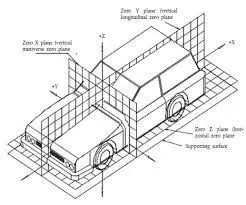
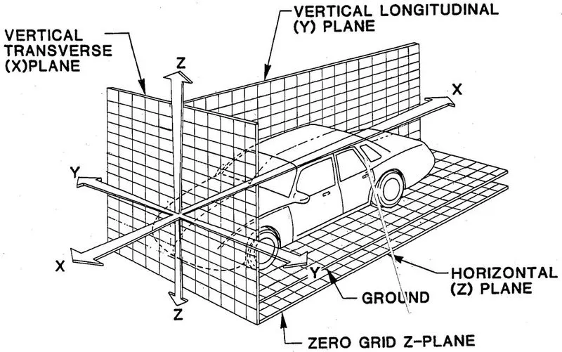
The body coordinate system has been widely used in the automotive industry for drawing of body parts, product and process design.
A coordinate system is a reference system of a set of points , lines and surfaces used to define the positions of points in space in either two or three dimensions.
In general BCS is also called as car line and body line .
The origin of the coordinate system (OX) is defined as the front centre of a vehicle, it indicates a length of car and the coordinate coordinate system (OZ) is below its underbody indicates the height of the car, and the coordinate system (OY) is stating point is the centre of car body indicates width of the car.
To represent the position of biw car parts,welding fixture and its unit assemblies with its individual parts (e.g. mylars(the parts which are in contact with panel)) in 2D drawings, their respective positions are shown with reference to (X=0,Y=0,Z=0)positions.
In short it shows in 2D XY, YZ or XZ coordinate position of BIW welding fixture parts or assemblies with reference to origin X=0,Y=0,Z=0
Let us consider a situation if individual fixture designer starts designing a part or panel on their default axes system then it will be difficult to assembly or position the part with respect to each other.
7.Elaborate Body plane system & its essentials.
These are reference planes in an automotive car. These are used to define the GD & T of all car parts in an automotive domain. Body planes are three mutually perpendicular imaginary planes. These are generally considered to be present at the driver position or sometimes at the engine location or at the front end of the car depending on the customer.The measurements from the bod planes to the parts are called as bodyline dimensions.The bodyplanes are also called as
FOL - Front O Line
COL - Centre O Line
BOL - Body O Line
FOL or X Axis - F/A Front Aft
COL or Y Axis - C/C Cross car
BOL or Z axis - U/D Up Down