Week 2:- BiW Fixture Basics Challenge
PROJECT EXECUTION
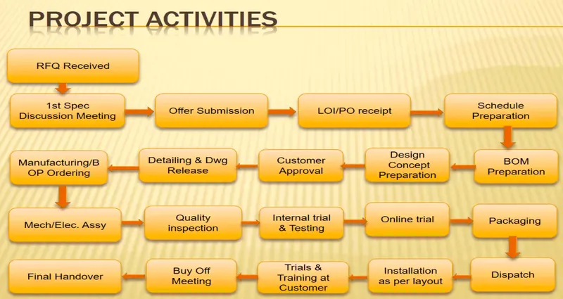
Request for Quote (RFQ)
- The first and foremost step in the process of project execution activity is receiving request for quote from the customers with the requirements and specifications.
- The RFQ contains the quantities and specifications of the product which will be send to various suppliers to figure out the best quote for the quantity they need.
- RFQ are generally used by companies for large scale procurement and used to solicit vendors and suppliers to narrow down choices for project bids.
1st Spec Discussion Meeting
- Upon receiving RFQ the Supplier Team huddles for a discussion to understand the voice of the customer and their requirements.
- They start the benchmarking processes and validate their abilities to meet the customer requirements in the best possible way.
OFFER SUBMISSION
- Based on the outcomes a detailed offer is proposed which contains details such as Total Estimated cost of the project, Tentative Delivery timeline, Setting expectation of how project activities are executed ,Customer -Supplier contract and guidelines and request for further detailed information.
- Thus the Offer is very detailed and unique to potentially grab the attraction of the customer and to differentiate from its competitors.
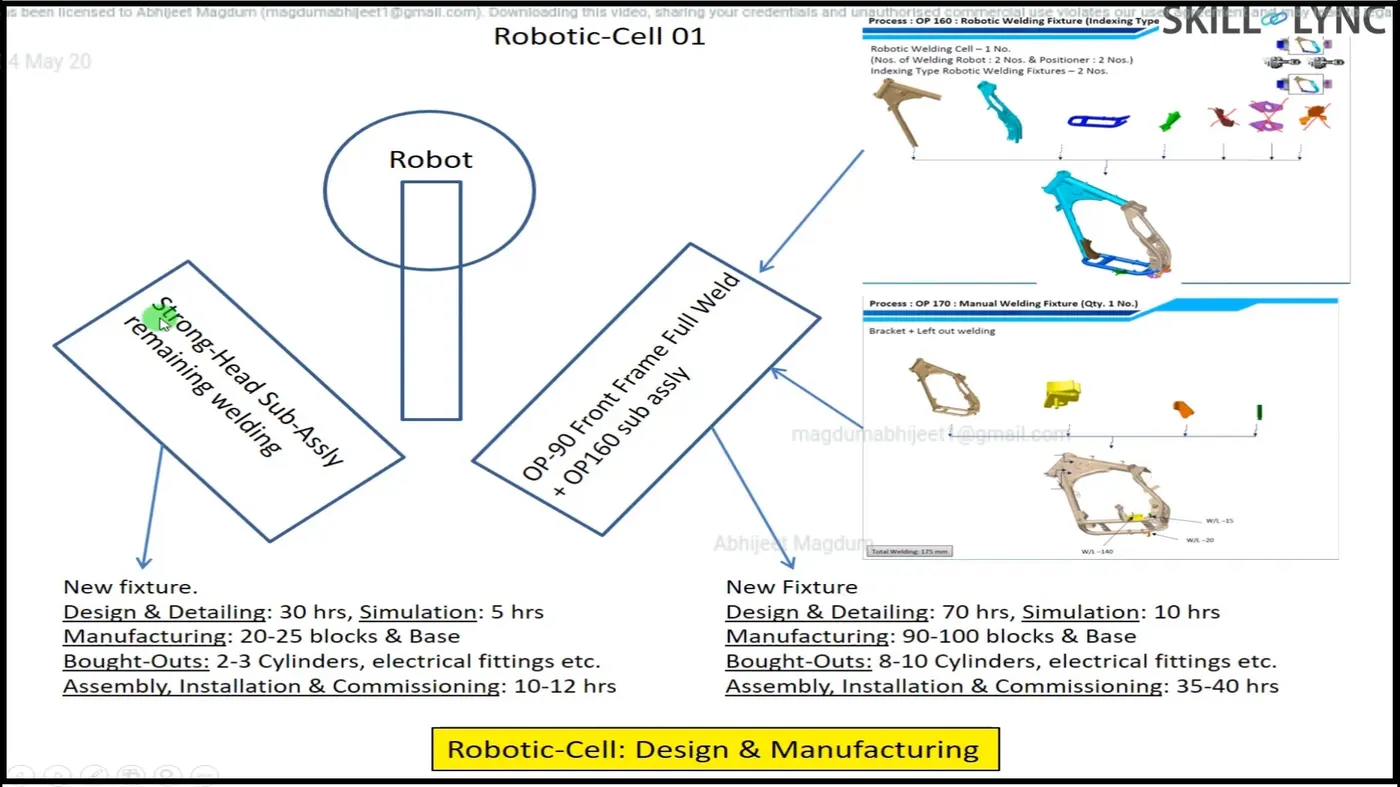
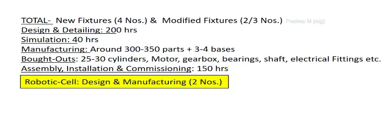
ROBOTIC CELL DESIGN TECHNICAL OFFER
LOI/PO RECEIPT
A successful Project proposal will receive a Letter of Invitation or Purchase Order receipt. Thus this embarks the Project kick off and the supplier starts to prepare a Project Schedule. In this phase, Technical details of the parts to be manufactured is also received.
PROJECT SCHEDULE
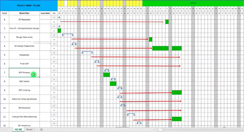
Project Management tools such as CPM, Gantt Chart or software such as Primevera, Windchill are used to schedule detailed project activities for the timeline. A detailed schedule is essential to track the project activities and to acheive critical milestones like, Design, BOM Preparation, Raw Material Purchase, Production, Quality Checking, Installation , etc., and would lead to successful completion of Project on time.
BOM PREPARATION:
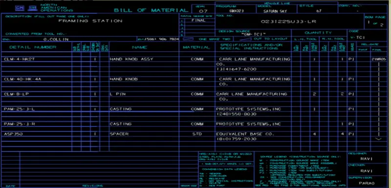
Based on the LOI Review meeting the parts for the fixtures are categorized and a detail Bill of Materials is prepared.
DESIGN CONCEPT PREPARATION:
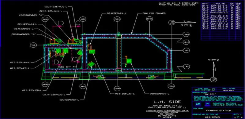
With BOM being prepared concept sketch is developed through Ideation and carry over study to develop the base,pin, stand, clamp units. This will follow all the specifications and guidelines defined by the client.
CUSTOMER APPROVAL STAGE:
The prepared concept will be send to customer to validate all details and for an approval. Any changes or modifications will be notified by the client and subsequent changes are made.
DETAILING & DESIGN STAGE:
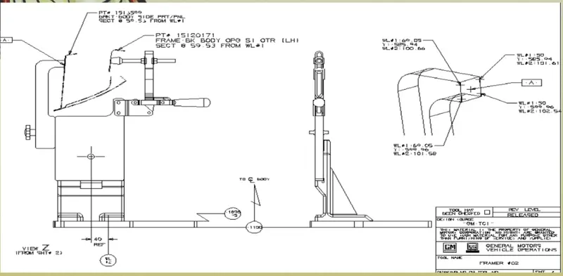
After the approval from the customer, the fixtures design process and detailing will start. All the parts to be produced are designed in the CAD software. The concept will be validated through simulation softwares and then a Manufacturing BOM is prepared.
MANUFACTURING/BOP ORDERING
The BOM will be cross checked by the Quality Team to verify the process and then the Manufacturing Team will start procurement of parts for manufacturing. Developement Stage will carryout the feasibility report to analyse whether the design is manufacturable and based on the DFM reports. The Production phase will start after conformance with Quality Team and Design Team.
MECHANICAL ELECTRICAL ASSEMBLY
The Next stage of Fixture Design is Assembly. A detailed Assembly procedure is developed and the parts are assembled and mounted for inspection.
QUALITY INSPECTION
The Quality inspection stage will verify all the units using CMM and other inspection devices and the quality report generated through CMM will be compared with the initial drawing release. After approval from the Quality team a physical simulation environment is set up to do a trial and run
INTERNAL TRIAL &TESTING
The internal trial and testing team will check the functions of the various fixtures like clamping and also measure the tolerance deviation and relative dimension between the mating parts. The initial trial and test will validate the fixture and material handling techniques and the parts will pass the Quality Check.
ONLINE TRIAL
Online Trial stage is the where all the automation functions of the fixtures are tested to check the efficiency of sensors in clamp opening and closing and the movement of the Clamp Handles and various movements. The Reed switch and sensor movement are validated. Once the fixtures reaches the quality benchmark level the testing and inspection is completed and parts are transferred for packaging
PACKAGING & DISPATCH
The manufactured fixtures after completing the production trials and online trials, is sent for packaging and dispatch. The number parts involved and layout of the assembly are transcended to the customers with the shipment details and Expected Delivery Date.
INSTALLATION AS PER LAYOUT
The dispatched parts are verified to supplier evaluation procedure to verify the quantity of the parts and the customer/client team will verify with the LOI and after approval the fixtures are assembled as per the layout and the Fixture assembly is ready for another trail at customer end
TRAINING & TRIALS AT CUSTOMER
In this stage the client workforce is trained about the fixture and how to operate with a simulated work environment. The efficiency and function of the fixtures are clearly demonstrated at the customer end.
BUY OFF MEETING
The Buy off meeting is done to get the feed back of the customer and if any modifications mentioned will be sought and any additional requirements prescribed will involve additional quotation. The service and warranty options of the fixture will also be discussed and the after sales team will create suitable documents for Service Engineers and an Service Level Agreement is signed.
FINAL HANDOVER
After completing all the stages the Fixtures is handed over to the customer.
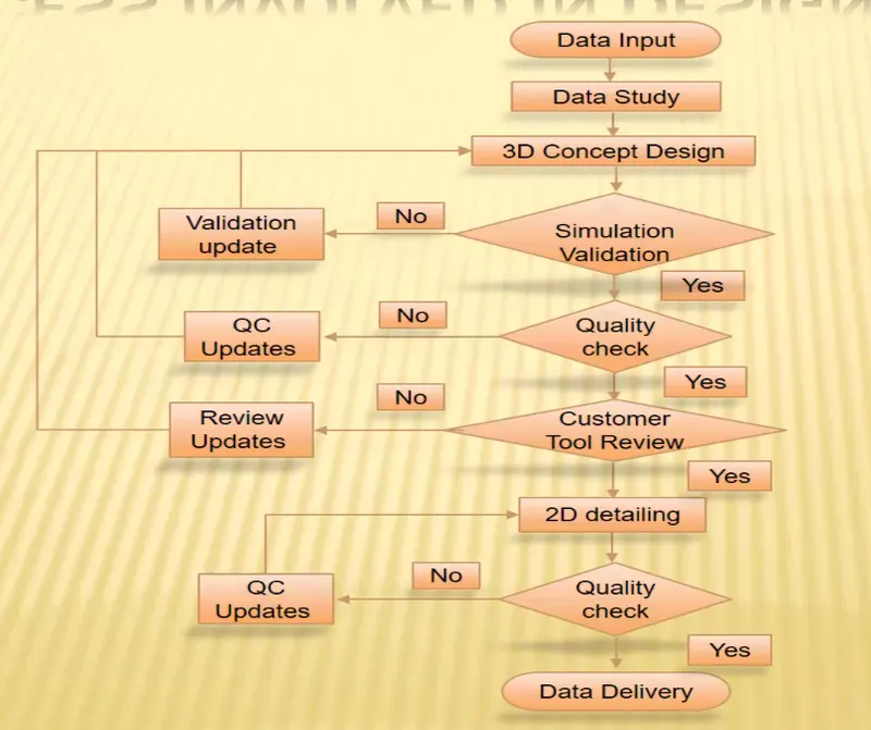
Process Flowchart in Fixture Design
JOINING PROCESS IN AUTOMOTIVE
The durability and performance of any structure is largely dependent on the quality and the design of the component joints. There are two types of joining processes used in Automotive Industry they are
- Mechanical Joining
- Metallurgical Joining
METALLURGICAL JOINING
Welding is the main operation used in Metallurgical joining type. The types of Welding are shown below
- In Metallurgical Joining process the workpiece is deformed at specified target either by applying current through pressure or through an electrode.
- While in Mechanical Joining process the Panels are joined by
- Mechanical Fastening and Self Piercing Riveting, Hemming and Adhesives
MECHANICAL FASTENING
Mechanical Fasteners are used where the weldability is poor or in dissimilar metals. It is used where high fatigue life and long tooling life is critical
Examples are Screws and Bolts
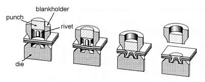
SELF PIERCING RIVETING
A high speed mechanical fastening process for point joining sheet material typically steels and aluminium alloys.
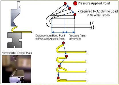
HEMMING
Enveloping the outer panel over inner panel along the edges of the sheet using Rollers are known as hemming.
ADHESIVE JOINING
Joining using special types of Adhesives like Mastic Points to achieve the influence of joining.
RESISTANCE WELDING
The most common type of welding used in the BIW Joining processes is resistance welding. The types of resistance welding are
- Resistance Spot Welding
- Resistance Projection Welding
- Resistance Seam Welding
Resistance welding is made by conducting a strong current through the metal combination to heat up and finally melt the metal at localised points predetermined by the position of the electrodes and the workpieces to be welded.

Spot welding, which can be automated combined with robots and manipulation systems is the most common joining process especially in high volume manufacturing lines and has in particular been the main joining process in BIW panels
RESISTANCE SPOT WELDING
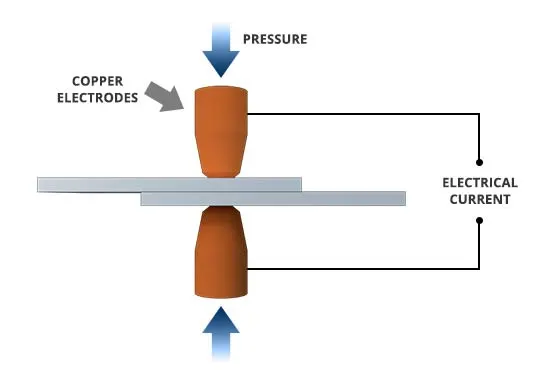
Resistance Spot Welding process
- The process involves applying pressure and heat to the weld area using shaped alloy copper electrodes which convey an electrical current through the weld pieces.
- The welding heat is generated by the electric current, which is transferred to the workpiece through copper alloy electrodes.
- Copper is used for the electrodes as it has a high thermal conductivity and low electrical resistance compared to most other metals, ensuring that the heat is generated preferentially in the work pieces rather than the electrodes.
APPLICATIONS
- Resistance Spot Welding which is a pressure welding process is cost effective technology used in joining Automotive BIW parts, reinforcement structures, frames.
- The Weld quality is better which can be simulated with required parameters .
- Effective in joining thinner materials with high production rate.
RESISTANCE PROJECTION WELDING.
Resistance Projection welding is a slight modification of Spot Welding where the current applied through two flat electrodes are much stronger and therefore used for joining Thicker materials.
APPLICATIONS
The strength of the weld quality is better hence used in joining thicker materials. Eg. Weld Nuts.
RESISTANCE SEAM WELDING
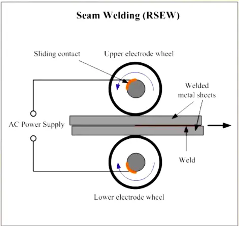
In seam welding a series of overlapping nuggets is produced, usually by replacing the conventional spot welding electrodes by wheels that turn as the parts to be welded are fed between them. The process thus produces a continuous leak-tight seam.
APPLICATIONS
Seam Welding is mostly applied in manufacturing of containers, radiators and heat exchangers.
FUSION WELDING
Fusion Welding is a type of welding where joining is achieved through heat by fusing the two materials through an electrode.
External application of pressure is not required.
The types of fusion welding process are
- Arc Welding
- Resistance Welding
- Gas Welding
- High Energy Welding
ARC WELDING
ARC Welding process involves either consumable electrodes or non consumable electrodes.
Arc is produced between the tip of electrode and workpiece by use of AC or DC Power
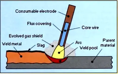
TYPES of ARC WELDING
MANUAL METAL ARC WELDING
It is also known as Shielded metal arc welding which is a stick welding process where both the electrode rod and workpiece metal fuses to create a weld
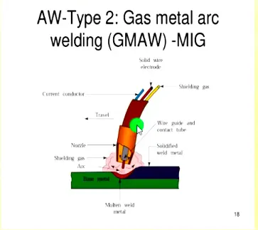
METAL INERT GAS WELDING
In MIG welding process a stream of Inert gas is passed to the arc for welding
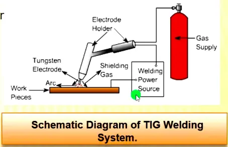
TUNGSTEN INERT GAS WELDING
TIG Welding uses a non consumable tungsten electrode along with an inert gas with the aid of filler rod and weld head
3-2-1 PRNCIPLE
- 3-2-1 Principle or Taylor's principle is way of arresting the degrees of freedom to completely fix the component with respect to the primary, secondary and tertiary datum planes.
- Fixture Design process involves accurate and correct orientation of workpiece with respect to the cutting tool or inspection device with rigid clamping and fixation of workpiece.
- A workpiece in free space has 12 degrees of freedom
- 6 Translational ( positive and negative directions of X,Y,Z axes)
- 6 Rotational ( Clockwise and Anticlockwise with respect to X,Y,Z)
- Thus a fixture uses 321 principle to constrain the motions of the workpiece by suitable holding devices during various operations.
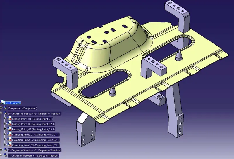
Translational Motion along Z ( + & -), Rotational Motion along X and Y ( C & A) are arrested using primary resting points
Translational motion along X and Y ( C&A) are constrained using secondary location
Rotational Motion along Z is restricted in Tertiary Plane.
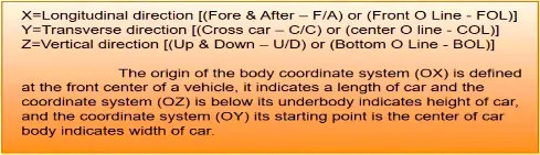
BODY COORDINATE SYSTEM
- It is a coordinate system consisting of set of points, lines and surfaces used to define to define the position of points in space in either two or three dimensions.
- It is also called as car line and body line
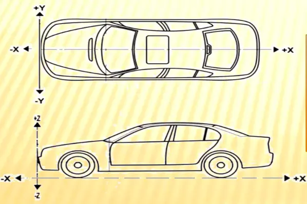
Body coordinate system is used in Automotive Industry for drawing of body parts, product and process design.
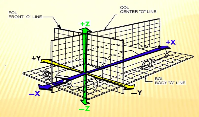
BODY PLANES
The Body planes are the reference planes used to define the GD&T of all the car parts in an Automotive Domain.
Thus the measurements from the body plane to the parts are called as body line dimensions.
APPLICATIONS
The applications of Body line dimensions are
- It defines the exact position of each vehicle body parts with respect to fixed origin
- It ensures a flawless design for assembly
- It assists in Quality Checks and in easy location of different parts
While designing, all the designs are carried out relative to the body lines (Fixtures, Turn tables) and helps in creating a standardised systems.
CONCLUSION
Thus basics of BIW Fixtures ,project execution activities, Joining Process , 3-2-1 Principle and Body Planes are explained in the report.