Week 2 Bevel Gear Challenge
OBJECTIVE 1
Grid Dependency Test
During the structural analysis of any given geometry, a mesh is generated in each case. This mesh makes it easier to decide how much total deformation or the amount of stress intensity takes place at each of the nodes and the elements in that particular. Therefore, a mesh is a collection of a large number of elements and nodes arranged in a particular order.
A mesh and a grid are nearly the same. There is no specific method to differentiate between a mesh and a grid. In the case of a grid, there are specific simulation elements with a well-defined structure along with the square and rectangular alignment. But a mesh is used in a general sense where elements of various shapes are combined together that may be unstructured and sometimes is a combination of elements of different types in the same mesh.
In a grid dependency test, the size of the elements in that grid is made finer and finer to get better and more accurate results of total deformation, stress intensity, von-missus stress, and many other conditions. Thus, in this case, the accuracy of the results is dependant on the size of the elements in the grid, hence the name grid dependency test. The smaller the size of the elements, the more the number of nodes, the finer the grid, the more accurate will the results be.
Unlike this, in the case of mesh independency test, the mesh is made so fine, that is the size of the elements is made so small that any further changes in the size of the elements or even if the mesh is made finer there won’t be any changes in the obtained results.
Measurement of values of Total Deformation, Equivalent Stress, and Equivalent Elastic Strain.
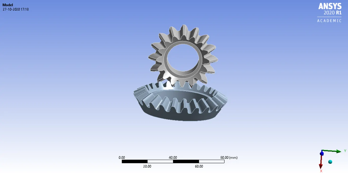
The given module was inserted into the mechanical GUI. Since the center portions of the driven and the driving gear were not necessary, they were edited in the SpaceClaim GUI. The geometry has been shown below.
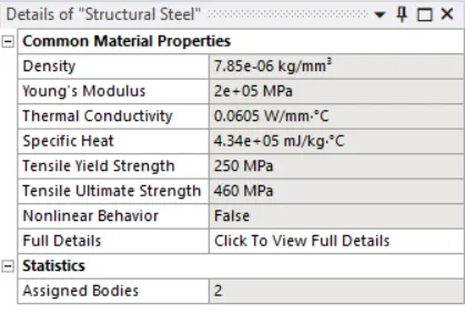
The material used for the entire stimulation was structural steel. The details of this material have been mentioned below.
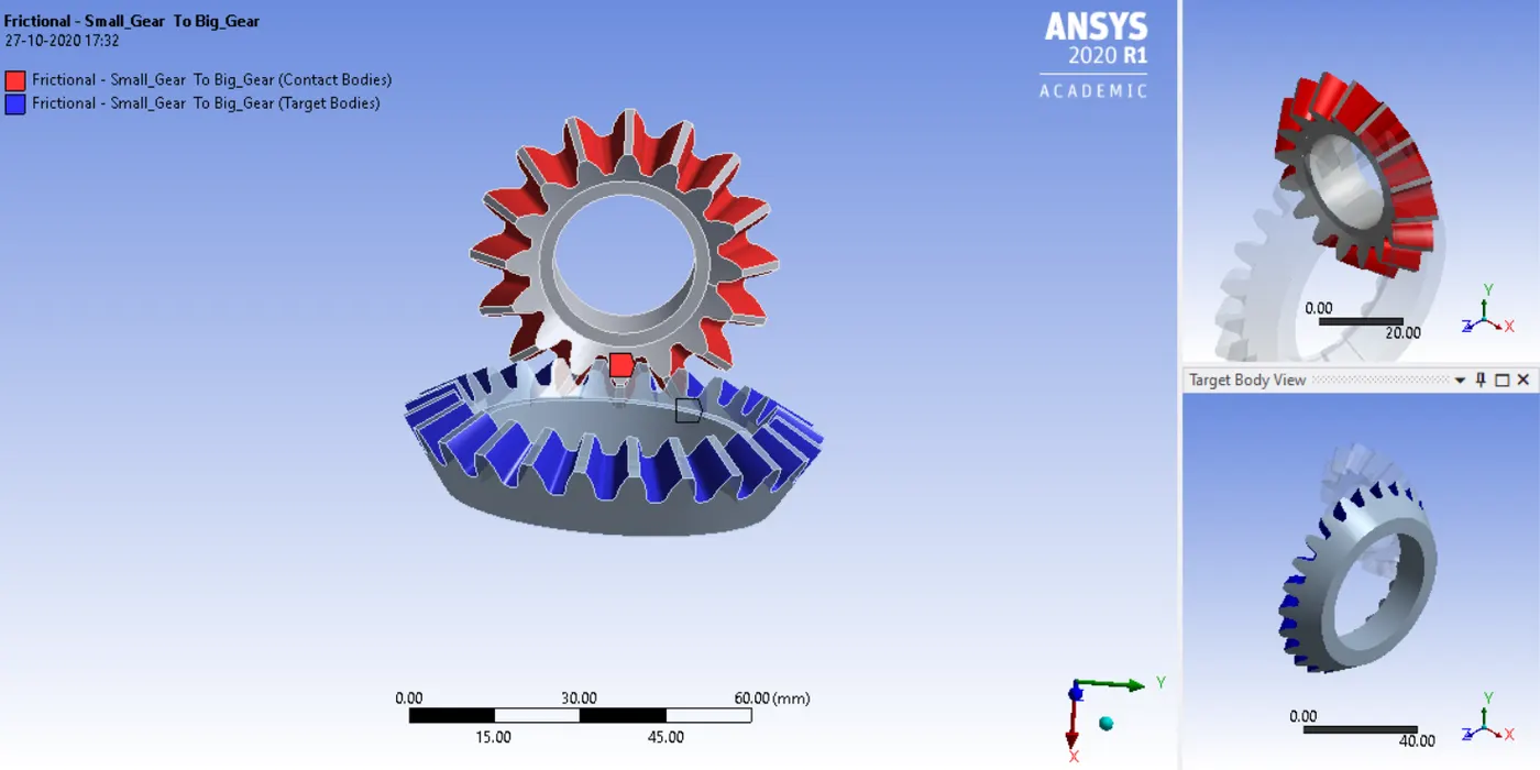
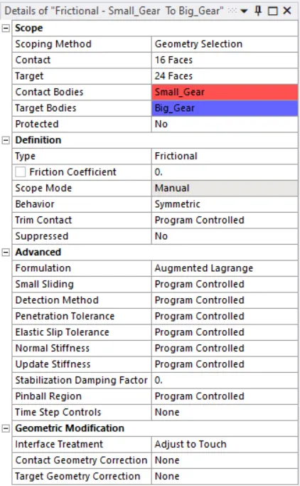
Following the assigning of material, the connections in the bevel gear were specified. The Small_Gear was kept as the contact body and the Big_Gear was kept as the target body. The faces of the respective gears were selected and specified. The connections and their details have been mentioned.
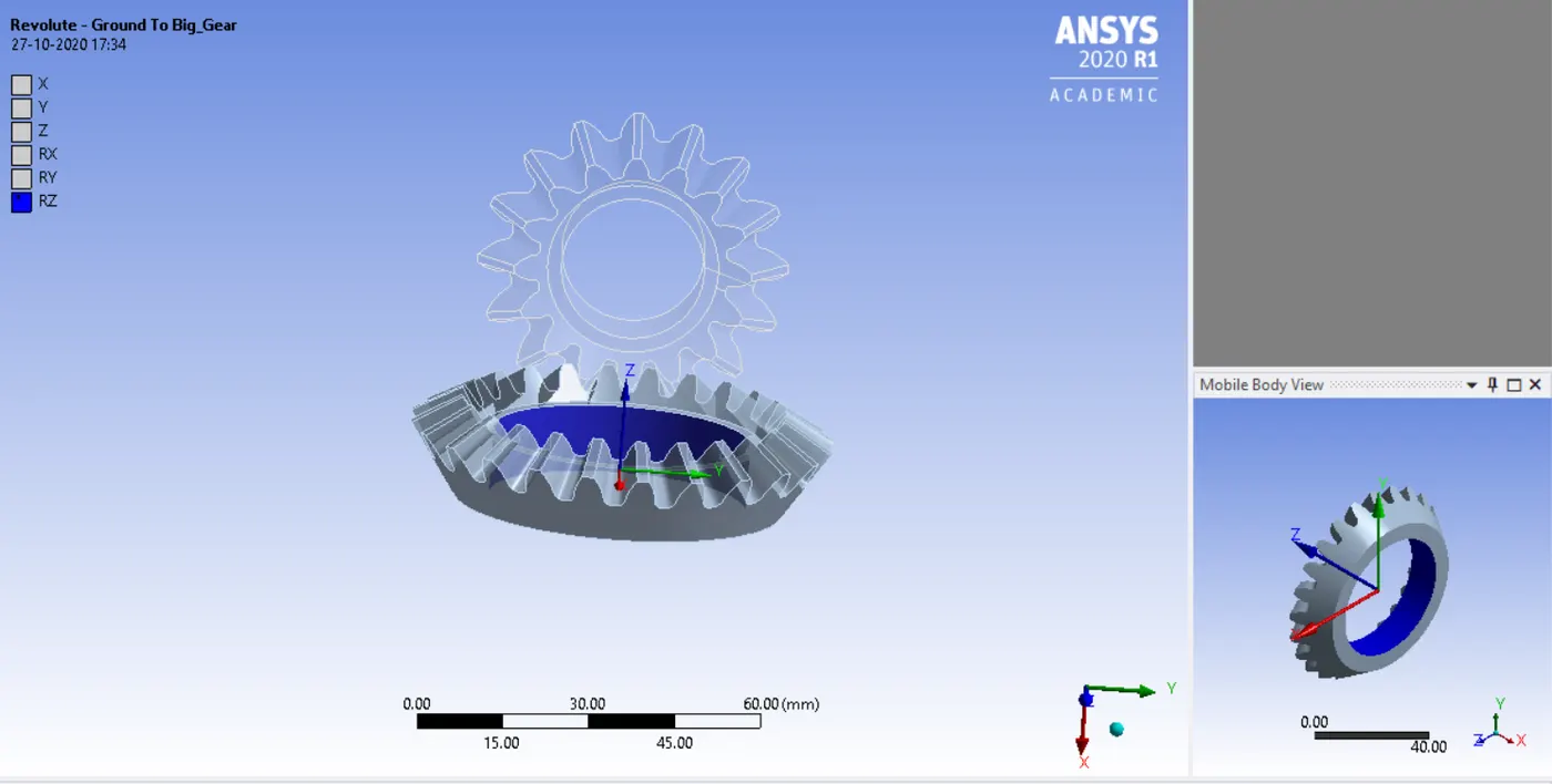
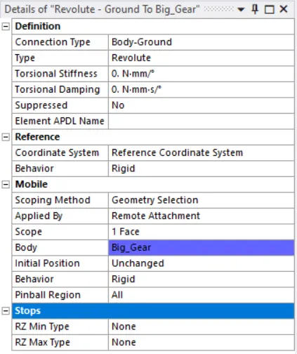
The joints in the gears were also specified. The details of these joints are mentioned below.
1. Revolute Joint - Ground to Big_Gear
2.Revolute Joint - Ground to Small_Gear
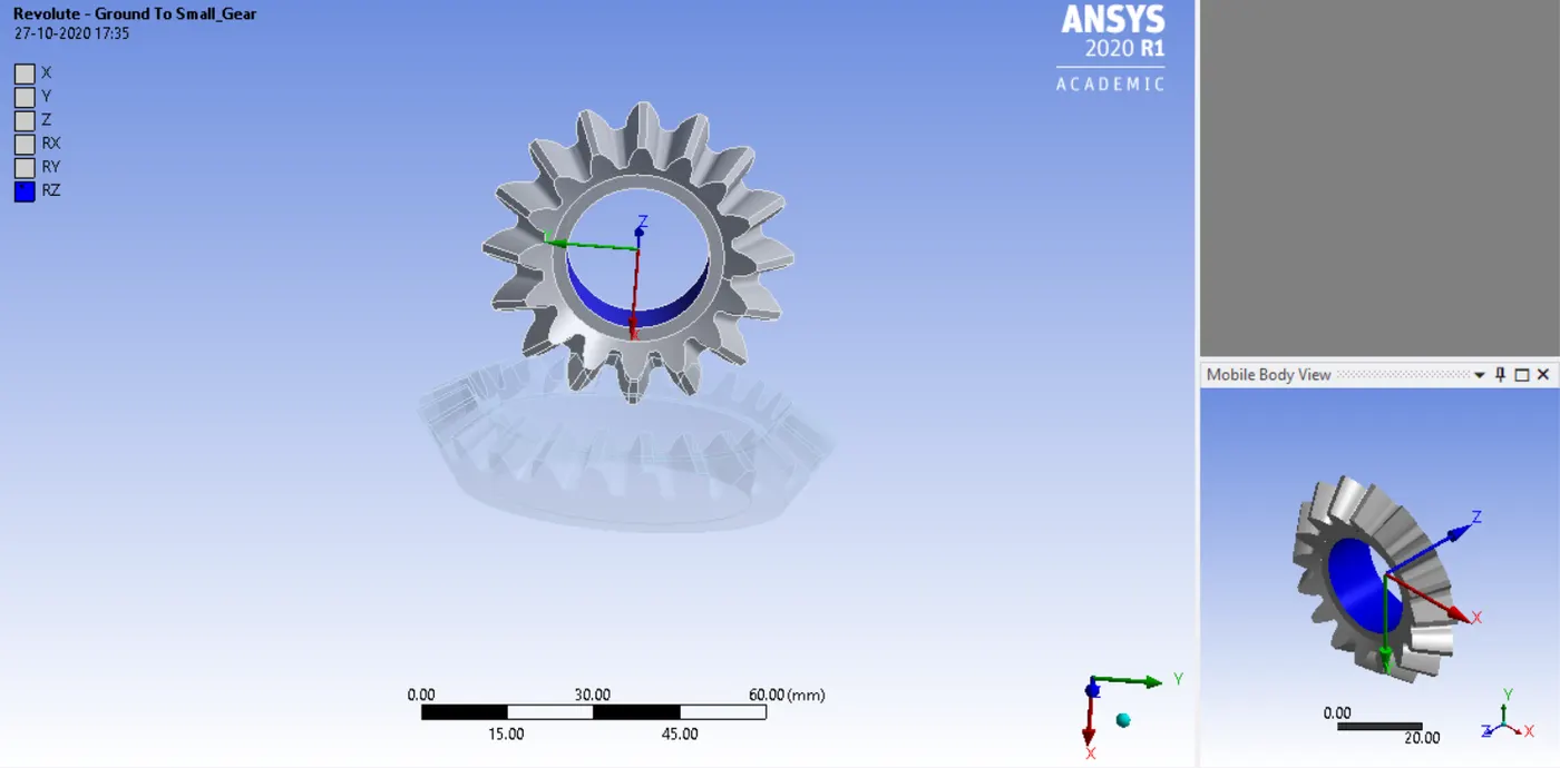
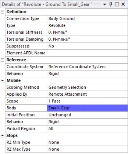
For the revolute joints, it was made sure that both of them rotated about the z-axis direction. The small gear in the clockwise direction and the big gear in the anti-clockwise direction.
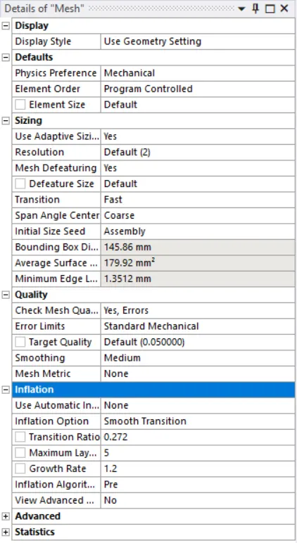
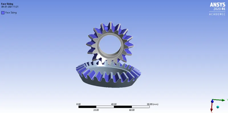
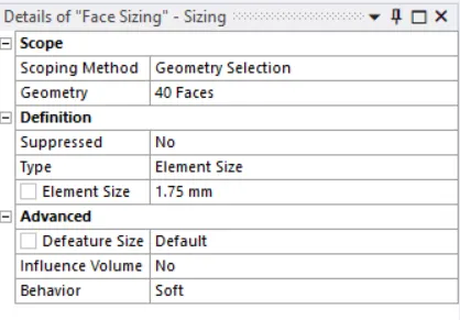
Following this procedure, the mesh was assigned to the given module. At first, a default mesh was used. It was found that the default mesh was too coarse for the stimulation to run successfully. Hence, a face sizing was inserted where each of the faces of both the gears included was selected and the element size was specified to 1.75mm respectively. The details of the default mesh and the face sizing used are mentioned.
Default Mesh - 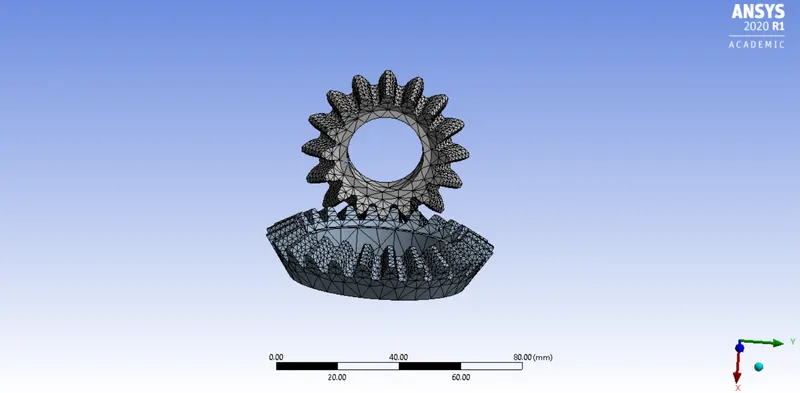
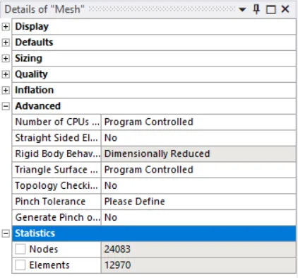
Face Sizing Used -
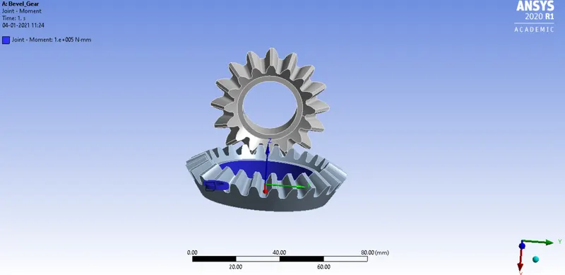
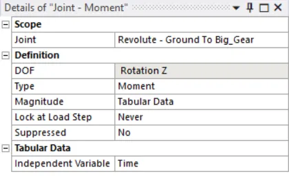
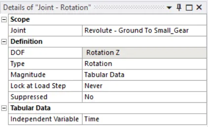
From the static structural, two joint loads were inserted – one for the big gear specified as joint moment and one for the small gear specified as joint rotation. The values for both of these joint loads were specified using tabular data. The details of the joint loads have been mentioned.
Joint load for Big_Gear - Joint Moment
Joint Load for Small_Gear - Joint Rotation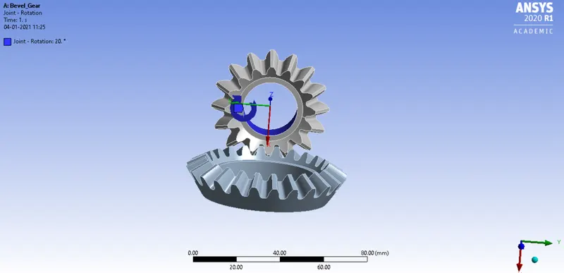
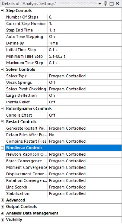
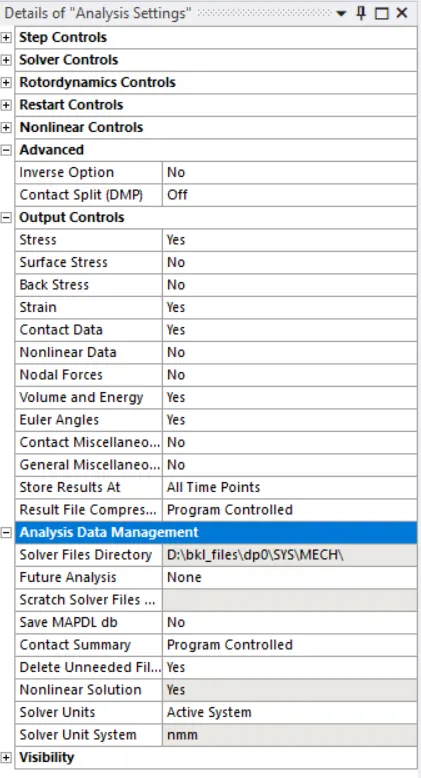
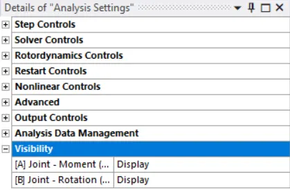
Following this, the details of the static analysis were specified and the gear was made to rotate for 6-time steps with the given changes -
For the given module, the results for total deformation, equivalent stress or Von-missus stress, and equivalent elastic strain or Von-missus strain were found out. The maximum and the minimum values of total deformation, equivalent stress, and equivalent elastic strain were observed carefully for the mentioned different mesh sizes and hence the aforementioned grid dependency test was performed on the given module of bevel gear using three different mesh sizes namely 4mm, 5mm, and 6mm.
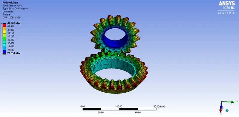
When the total deformation, equivalent stress, equivalent elastic strain was calculated, the results were different for different mesh sizes. The results were first calculated for the default mesh.
|
Condition |
Minimum Value |
Maximum Value |
|
Total Deformation |
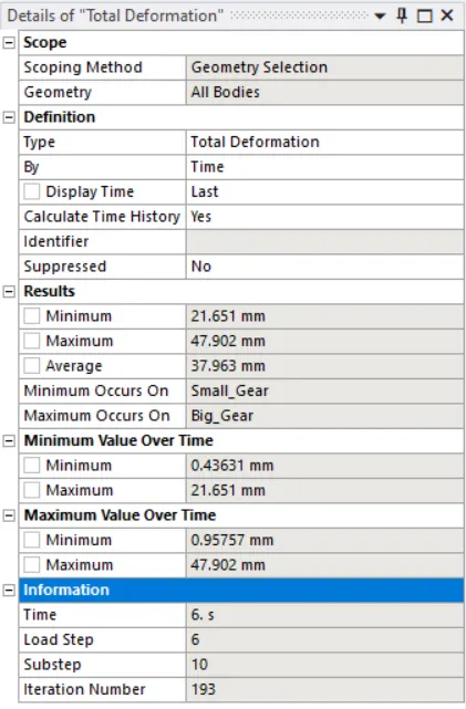
21.651mm |
47.902mm |
|
Equivalent Stress |
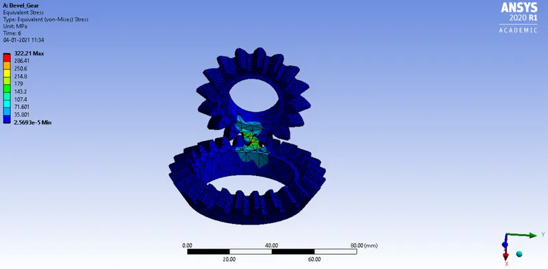
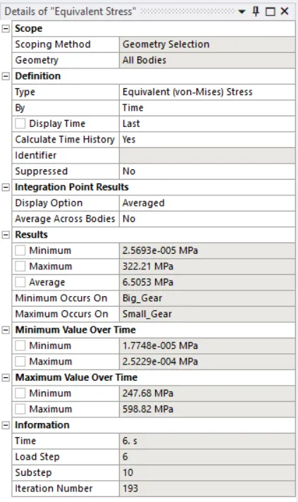
2.5693e-5MPa |
322.21Mpa |
|
Equivalent Elastic Strain |
2.7898e-10 mm/mm |
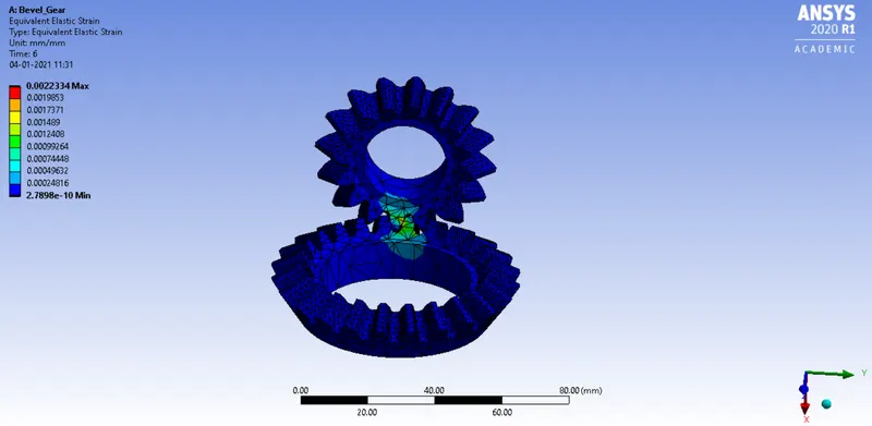
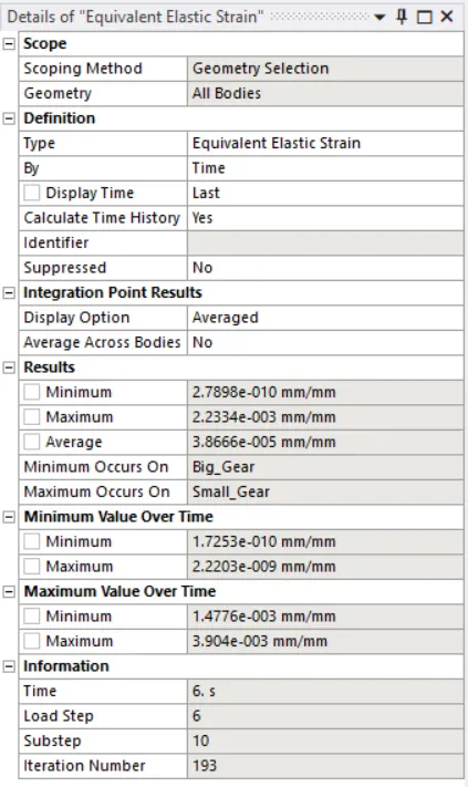
0.0022334 mm/mm |
The details of the total deformation, equivalent stress, and equivalent elastic strain for the default mesh have been given below.
Total Deformation –
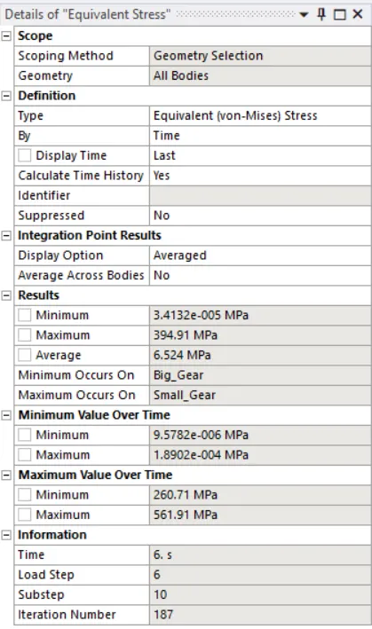
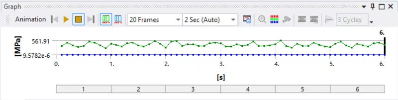
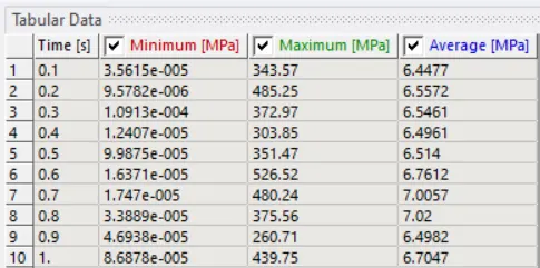
Equivalent Stress / Von-Missus Stress –
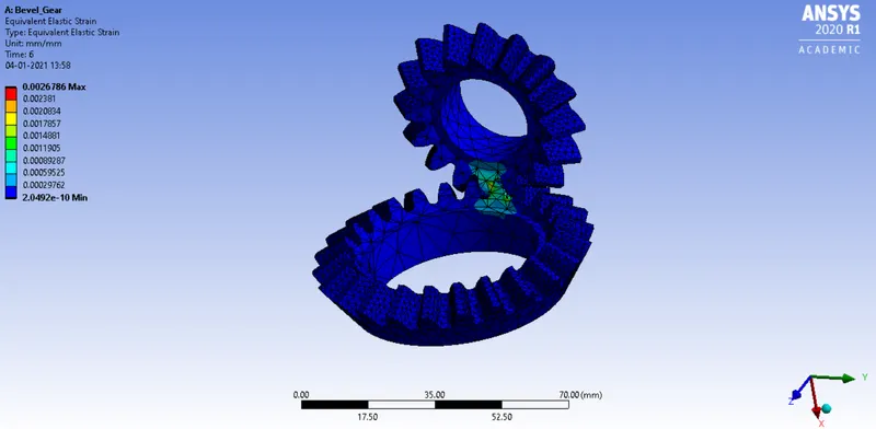
Equivalent Elastic Strain / Von-Missus Strain –
The next simulation was conducted for the mesh having an element size of 4mm.
Face Sizing Used – 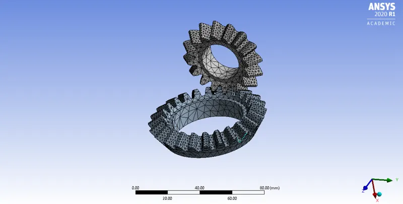
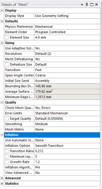
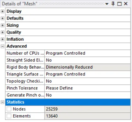
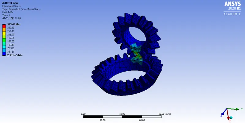
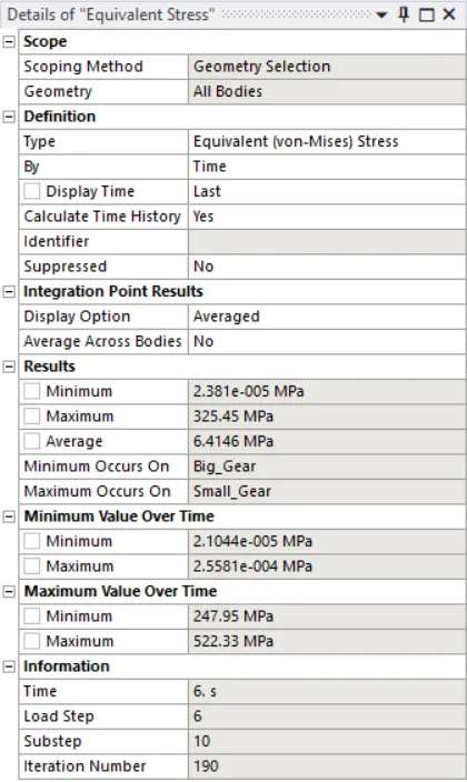
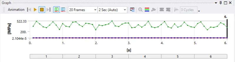
The maximum and minimum values for the total deformation, equivalent stress, and equivalent elastic strain are given.
|
Condition |
Minimum Value |
Maximum Value |
|
Total Deformation |
21.651mm |
47.902mm |
|
Equivalent Stress |
2.381e-5MPa |
325.45MPa |
|
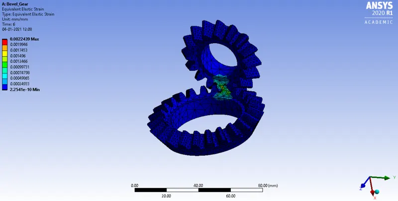
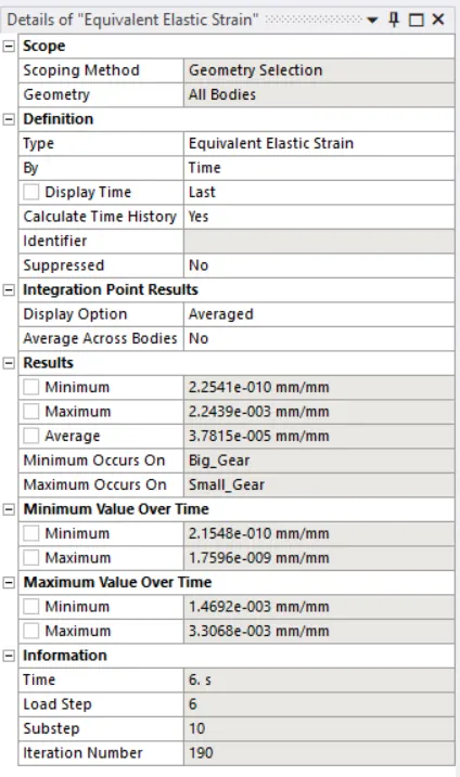
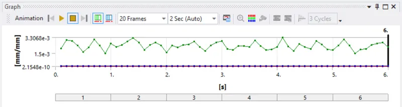
Equivalent Elastic Strain |
5.7266e-13 |
2.2113e-5 |
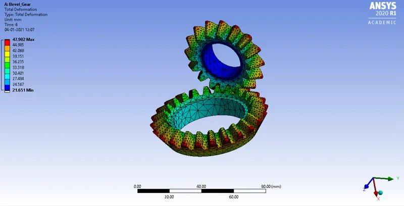
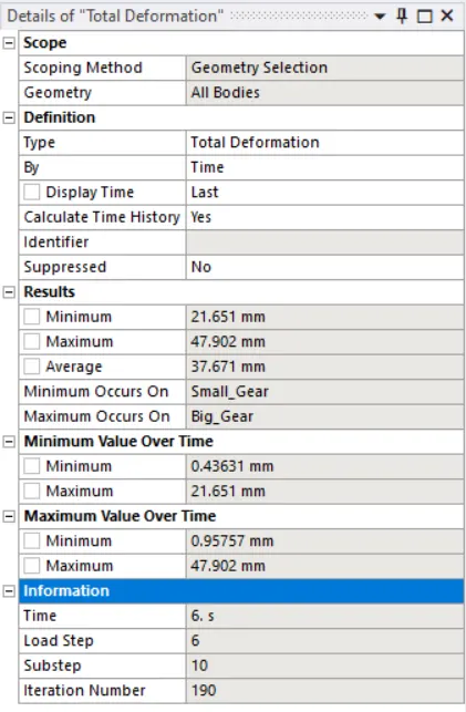
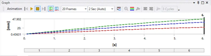
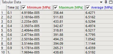
The details of the total deformation, equivalent stress, and equivalent elastic strain have been mentioned below.
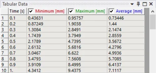
Total Deformation –
Equivalent Stress / Von-Missus Stress –
Equivalent Elastic Strain / Von-Missus Strain –
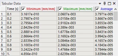
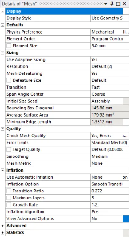
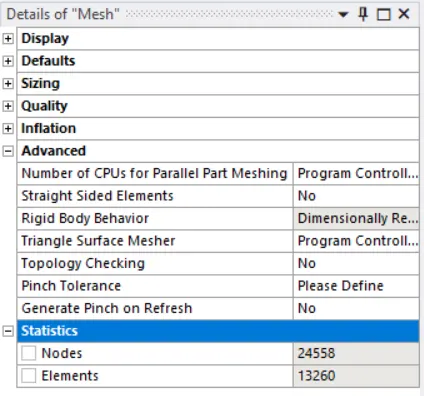
The third stimulation was conducted to calculate the total deformation, equivalent stress, and equivalent elastic strain for the mesh having the elements of the size 5mm.
Mesh Size details -
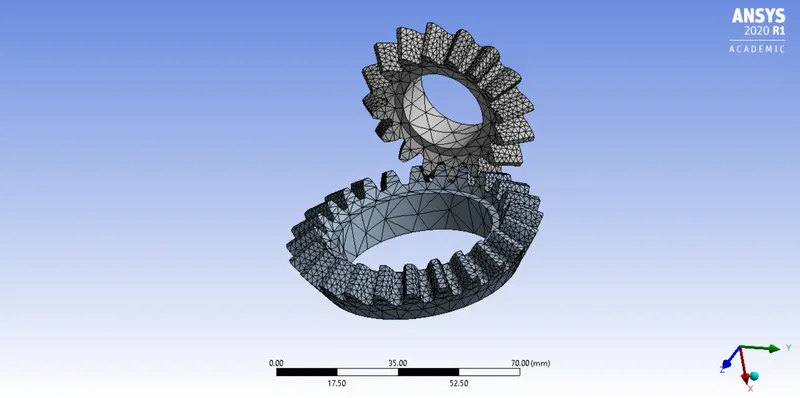
The maximum and the minimum values of the total deformation, equivalent stress, and equivalent elastic strain for the given module have been mentioned below.
|
Condition |
Minimum Value |
Maximum Value |
|
Total Deformation |
21.651 mm |
47.905 mm |
|
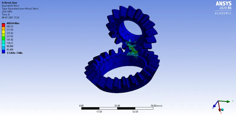
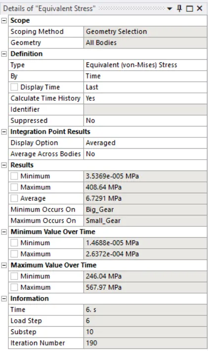
Equivalent Stress |
3.5369e-5 MPa |
408.64 MPa |
|
Equivalent Elastic Strain |
3.2247e-10 mm/mm |
0.0027655 mm/mm |
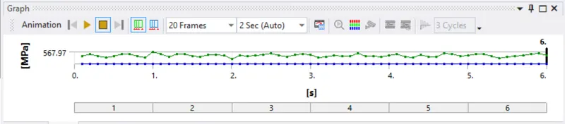
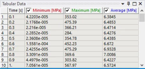
The details of the total deformation, equivalent stress, and equivalent elastic strain are given below.
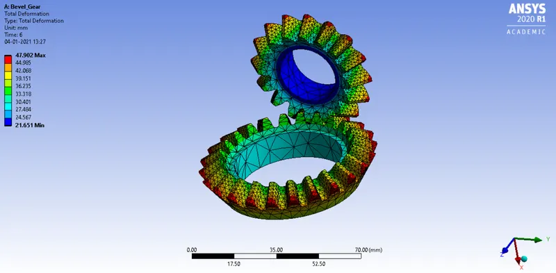
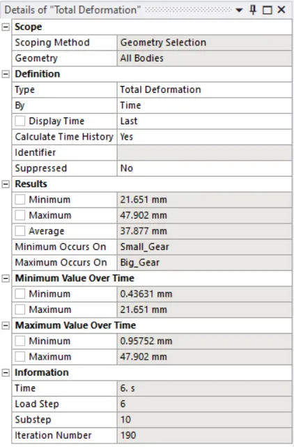
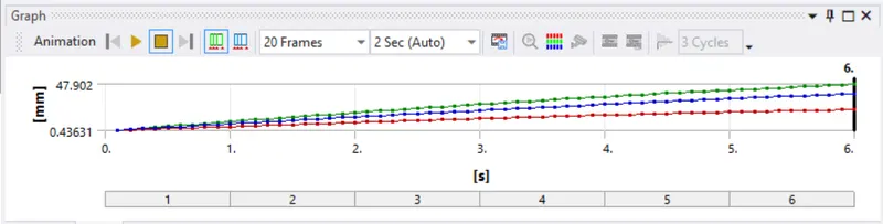
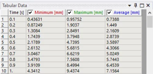
Total Deformation –
Equivalent Stress / Von-Missus Stress –
Equivalent Elastic Strain / Von-Missus Strain –
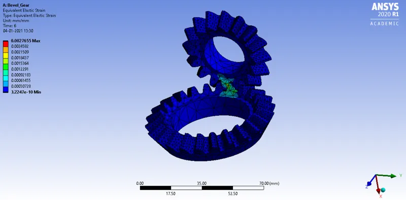
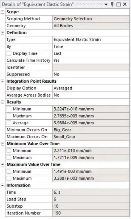
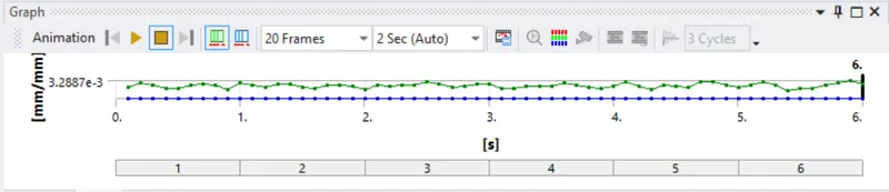
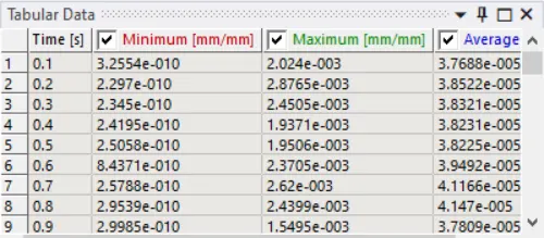
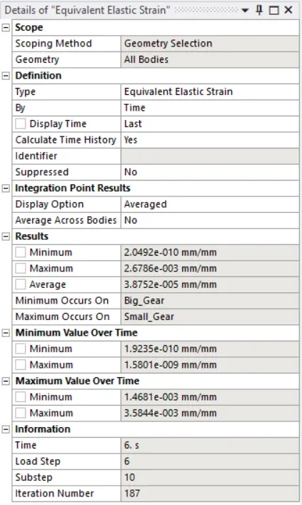
The fourth stimulation was conducted in order to calculate the total deformation, equivalent stress, and equivalent elastic strain for the given module with a mesh having an element size of 6mm.
Mesh Sizing Details –
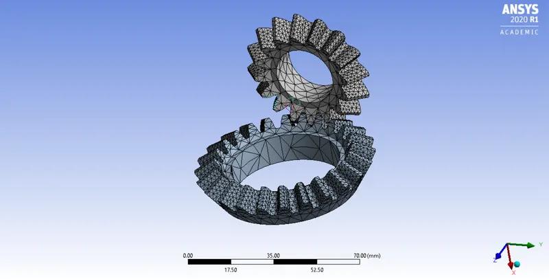
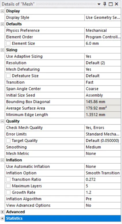
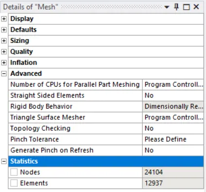
The minimum and maximum values for the total deformation, equivalent stress, and the equivalent elastic strain for the given module have been mentioned below.
|
Condition |
Minimum Value |
Maximum Value |
|
Total Deformation |
21.651 mm |
47.905 mm |
|
Equivalent Stress |
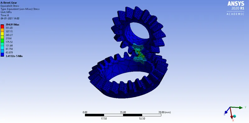
3.4132e-5 MPa |
394.91 MPa |
|
Equivalent Elastic Strain |
2.492e-10 mm/mm |
0.0026786 mm/mm |
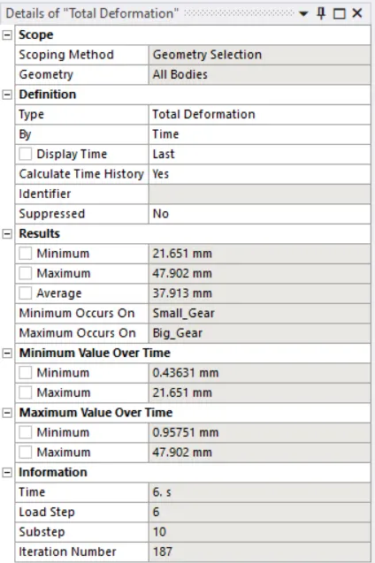
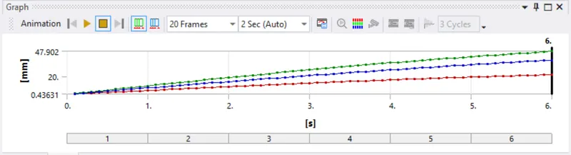
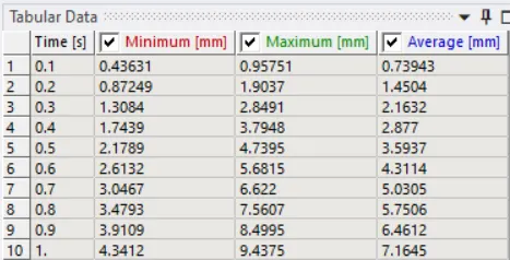
The details of the total deformation, equivalent stress, and equivalent elastic strain are given below.
Total Deformation – 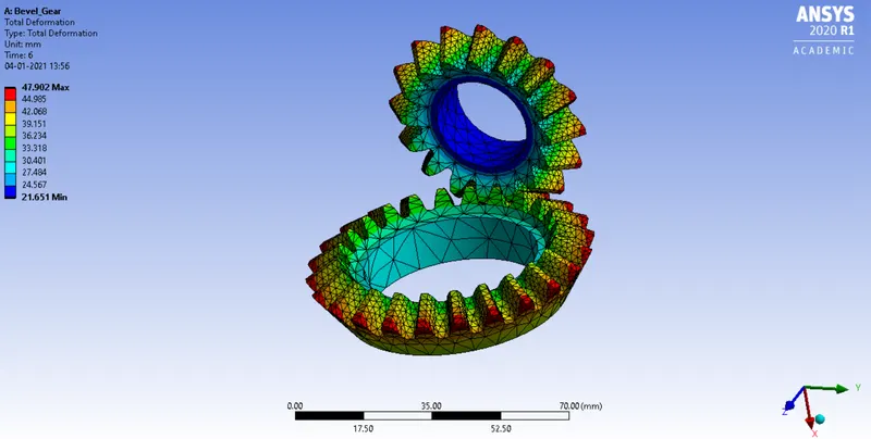
Equivalent Stress / Von-Missus Stress –
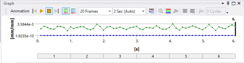
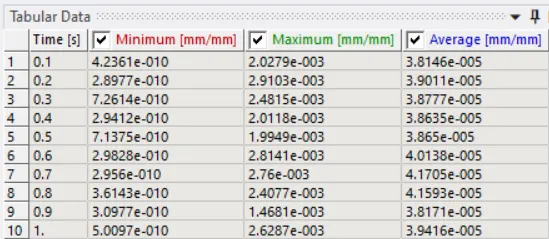
Equivalent Elastic Strain / Von - Missus Strain –
Conclusion
Following this, the stimulation was made to run for meshes of different element sizes respectively 4mm,5mm, and 6mm. A comparison between the default mesh and the meshes of three different element sizes were made.
From this comparison, it was observed that
- Although the minimum and the maximum values of the total deformation, equivalent stress, or Von-missus stress and equivalent elastic strain or Von-missus strain were equal, the accuracy in the results was more as the element size was decreased.
- There was an increase in the number of nodes and elements as the mesh was made finer.
- The maximum and the minimum values for the total deformation, equivalent stress, and equivalent elastic strain differed from the mesh of one element size to another although the differences were very small.
- The maximum and minimum values for total deformation were the same and for equivalent stress, the equivalent elastic strain was found out to be the least for the mesh having the element size of 4mm and the highest for the mesh having the element size of 6mm
The links for the stimulation videos of the total deformation, equivalent stress and equivalent elastic strain for the respective meshes have been mentioned below