Week 2 Bevel Gear Challenge
Bevel Gear Report
Aim:
1)Write a few words on what a grid dependency test is and its use.
2)Perform a grid dependency test for the Bevel gear simulation for mesh sizes of 6,5 and 4 mm
3) Solve for Von-Mises stress, Equivalent elastic strain and Total Deformation using the previously mentioned mesh sizes.
4) Present your findings in an organized manner.
Procedure:
Grid Dependency Test: Mesh quality is vital when it comes to FEM. A good quality mesh will give you accurate results. A high-density mesh is always recommended for safe and realistic results. However, a highly dense mesh requires lots of memory and time.
So, it is up to the FEA Engineer it provide an optimum mesh size in such way that it doesn’t compromise on realistic results as well as not consume too much time. This is where Grid dependency test plays a key role. The test begins with a coarse mesh and is refined until an important result such as Equivalent Stress doesn’t change significantly with change in Mesh Size. This test will help us arrive at the optimum mesh size where time as well as accuracy of results are not compromised.
Bevel Gear Grid Dependency Test:
- Select Static Structural, drag and drop into Project Schematic.
- Choose material as steel, under Engineering Data.
- Under geometry tab, import the given Bevel Gear geometry, double-click to open SpaceClaim to register the model.
- Then in Mechanical Module, assign a frictional connection between the gear teeth. (Right to Left)
- Assign revolute joints to both the gear. (Ground to Big/Small)
- A mesh element sizes are varied for case to case.
- Face Sizing is done in every case for the faces on gear teeth at 1.75mm element size. This is done to generate a better mesh on the faces that are critical in the analysis.
- Under static structural tab, we enter the values of rotational motion of the two gears.
- The small gear is made to rotate up to 120deg in six steps of 20deg each.
- The Big gear is made to rotate with a moment of 100Nmm in counterclockwise motion.
- Total Deformation, Equivalent Elastic Strain and Equivalent Stress plots are requested from the solver as outputs.
- The same process is repeated for each case by changing the mesh size.
Case 1: Used mesh size = 6mm, carried out a static structural analysis to find out Equivalent stress, Total deformation and Stress intensity. Found location for possible fracture.
The results are given below:
Equivalent Stress: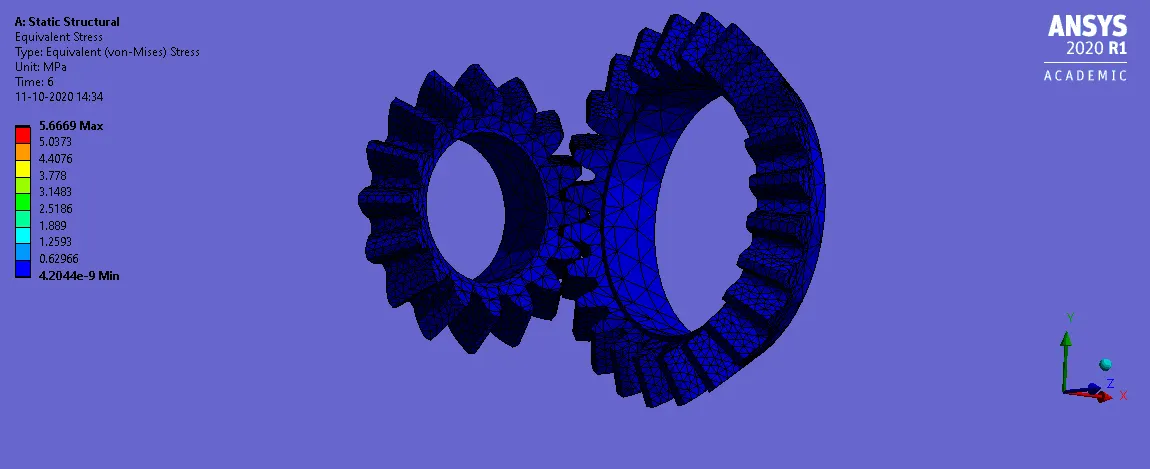
Equivalent Strain: 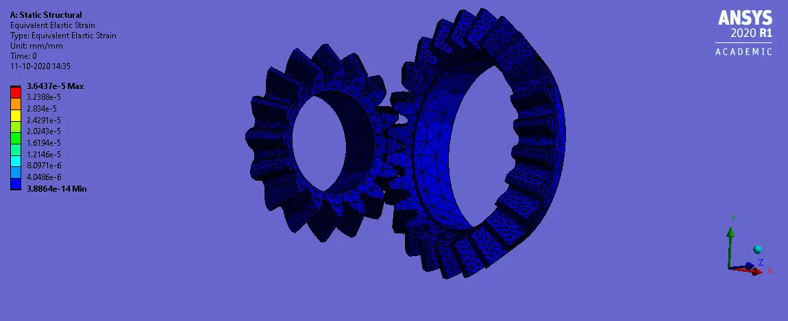
Total Deformation: 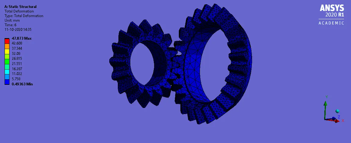
Case 2: Used mesh size = 5mm, carried out a static structural analysis to find out Equivalent stress, Total deformation and Stress intensity. Found location for possible fracture.
The results are given below:
Equivalent Stress: 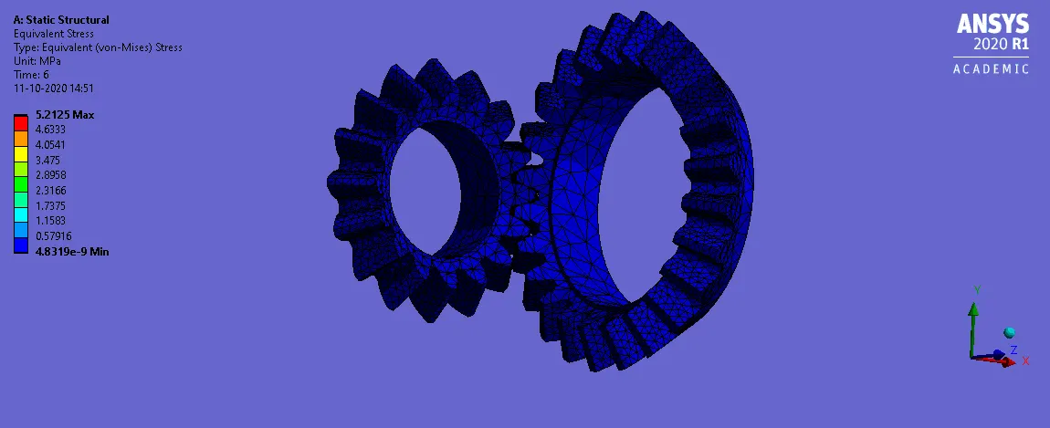
Equivalent Strain: 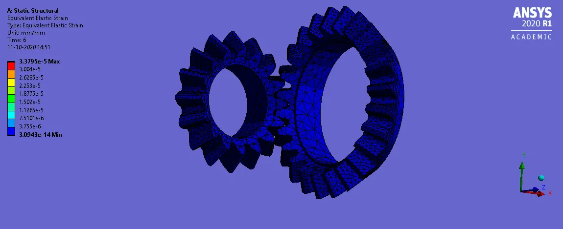
Total Deformation: 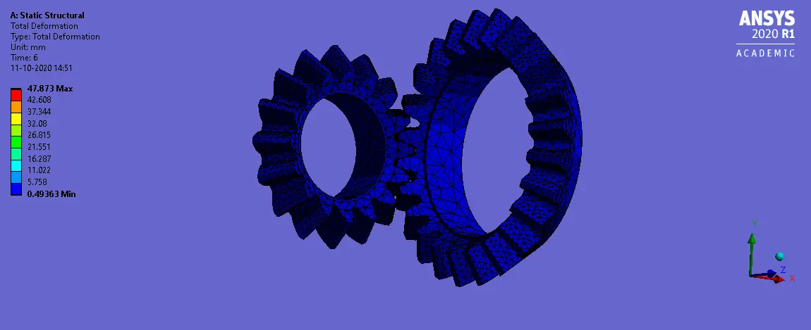
Case 3: Used mesh size = 4.5mm, carried out a static structural analysis to find out Equivalent stress, Total deformation and Stress intensity. Found location for possible fracture.
The results are given below:
Equivalent Stress: 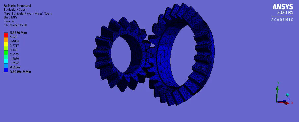
Equivalent Strain: 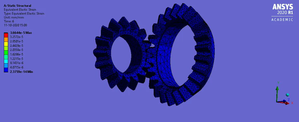
Total Deformation: 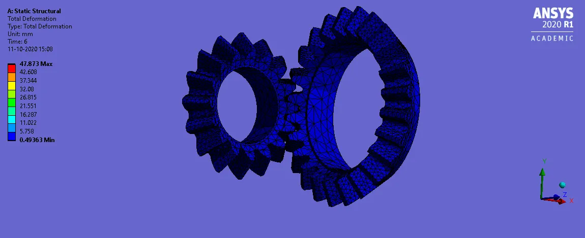
Conclusion:
We can infer the following data from each case.
|
Mesh Size(mm) |
Eq. Stress (N/mm2) |
Eq. Strain |
Total Deformation (mm) |
Time Elapsed (s) |
|
6 |
3.1928 |
2.36E-05 |
47.873 |
624 |
|
5 |
4.5906 |
3.09E-05 |
47.873 |
641 |
|
4.5 |
5.6576 |
3.66E-05 |
47.873 |
659 |
We can notice that the value of Equivalent stress and strain become better as the mesh size is dropped. At the same time, we can also observe that the time elapsed has increased as the mesh size decreased. This is because of the increased elements after decreasing the mesh size. This is where Grid Dependency test becomes useful to determine the optimum mesh size with respect to Time elapsed.