Week 2 Bevel Gear Challenge
Aim: Grid dependency test on bevel gear.
Objective:
1) Carry out a static structural analysis to find out Equivalent stress, Total deformation and Stress intensity.
2) Using three different sizes of mesh 4, 5 and 6 to perform grid dependency test.
3) Comparing the three results on the basis of solution.
introduction:
Grid dependence test is the term used to describe the improvement of results by using successively smaller cell sizes for the calculations. A calculation should approach the correct answer as the mesh becomes finer. Mesh convergence determines how many elements are required in a model to ensure that the results of an analysis are not affected by changing the size of the mesh. System response (stress, deformation) will converge to a repeatable solution with decreasing element size. In this case we have used three different mesh sizes coarse, medium and finer mesh. From this analysis we can determine the accurate solution for decreasing mesh size when it converges for each solution to solve in the given geometry which is bevel gear.
Procedure:
1) For bevel gear analysis, we use static structural tool in the analysis system tool box to define the geometry and other input parameters for
the same.
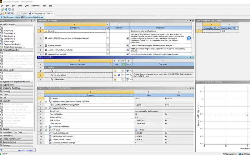
2) In the engineering data we input the material and its properties. In this case we are using structural steel and its properties are shown below.
3) Input the given spur gear geometry from the geometry tab. Naming them big gear and small gear.
4) In connection, we have to define the contact faces between the two gears of the geometry by selecting and deselecting as contact or target bodies. In contacts under connection tab we define the type of contact as frictional contact from right to left.
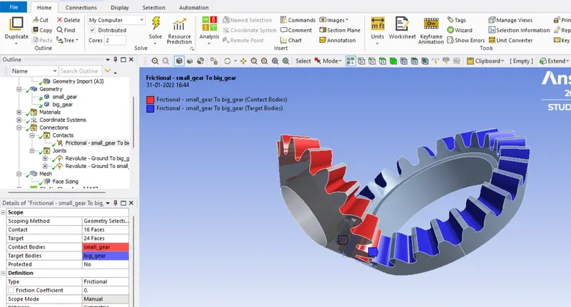
5) To define type of joint we use contact tab and specifying the body to ground connection type and setting as revolute type. Also scoping the geometry by selecting the inner face of the geometry.

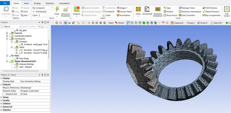
6) By opening the modelling the tab, we mesh the geometry with element size 4 and finer mesh size where contacts are present. Generating the mesh thereafter by right clicking on the Mesh icon.
7) After defining the contacts and joints, we open analysis setting where we define the revolution of gear in 6 steps with initial time step of 0.1 and max step of 0.2.
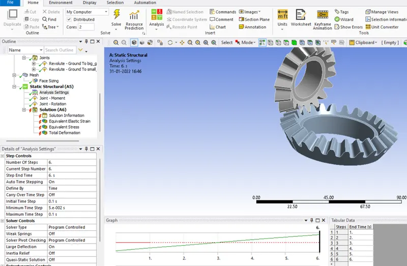
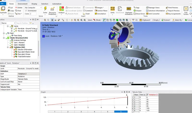
8) We select the first joint load from the static structural analysis tab for Big gear as rotational type and defining the angles starting from 0. 20, 40, 60, 80, 100, 120 degree in 6 steps to its each corresponding step. The left gear would be rotating anit-clockwise motion about Z axis comprising 20 degree for each step
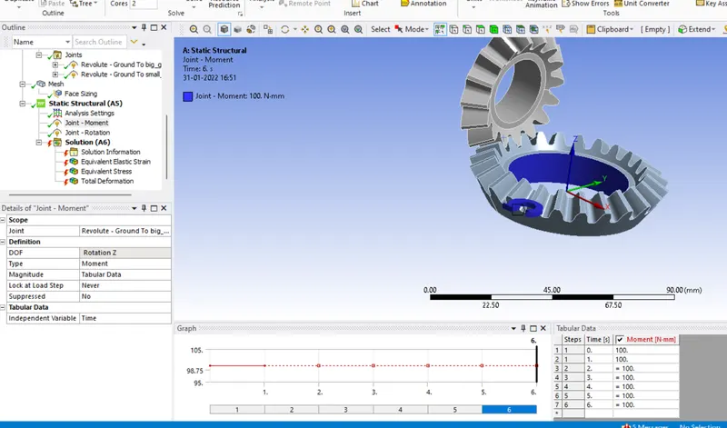
9) Now we define the Small gear with load joint by inputting the value of 100 N.m for every step in moment. This gear would be rotating clockwise direction.
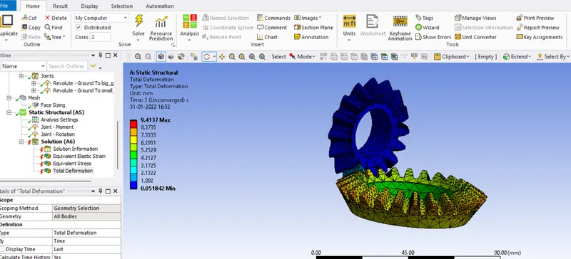
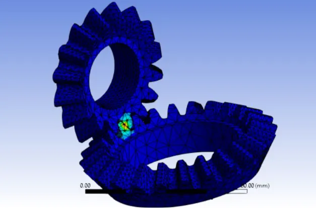
after running the simulation
A) total deformation
b) van stress
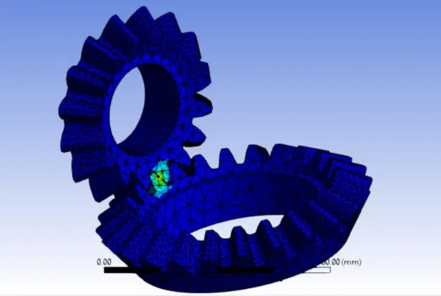
c) strain
Conclusion:
We can infer the following data from each case.
Mesh Size(mm) Eq. Stress (N/mm²) Eq. Strain Total Deformation (mm) Time Elapsed (s)
6 3.1928 2.36E-05 47.873 624
5 4.5906 3.09E-05 47.873 641
4 5.6576 3.66E-05 47.873 659
We can notice that the value of Equivalent stress and strain become better as the mesh size is dropped. At the same time, we can also observe that the time elapsed has increased as the mesh size decreased. This is because of the increased elements after decreasing the mesh size. This is where Grid Dependency test becomes useful to determine the optimum mesh size with respect to Time elapsed.