Week 2 Air standard Cycle
Air-Standard Cycle – Otto Cycle
Aim:
Development of code for air standard Otto cycle to extract the pressure vs volume diagram and to calculate the thermal efficiency of otto cycle.
Objective:
- To study the working of otto cycle.
- To develop the algorithm for calculation of state variable in otto cycle.
- To plot the state variable in the graph called pv-diagram.
- To calculate the thermal efficiency of cycle.
Description & Governing equations:
An engine is a machine which generate power through the combustion air-fuel mixture by providing heat at utmost pressure and temperature. During this combustion process the piston which is main part of engine goes back and forth to repeat the cycle. This cycle of intake, compression, combustion and expansion are governed by the specific air standard cycles. This air standard cycle provides the information about the process how they are happing inside the cylinder. The type engine decides which kind of cycle it is running in the process. As if it is petrol engine then it performs Otto cycle and if it is diesel engine then it performs diesel engine. Both the process is different but involve under the same piston-cylinder of engine.
Otto cycle is called constant volume cycle as the heat addition process happens at constant volume and heat rejection also. The process involves isentropic compression and expansion of air inside the cylinder. The heat addition is done by the spark plug in case of petrol engine and in case of diesel engine it is done by high pressured fuel spray following by auto-ignition phenomenon. The PV diagram tells us the pressure and volume condition at which the heat added and rejected during the process. There is T-S diagram which is temperature and entropy diagram for same PV diagram which tell us about the temperature changes with respect to constant entropy process. The actual PV diagram is totally different than that of air-standard cycle because of neglection of friction, mass factors of components and inertia of air flow. The main most important aspect of air-standard cycle and actual cycle is that in air-standard the working medium is ideal gas.
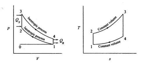
From the above PV diagram, we can see that the process is in cyclic nature. The process always starts from the heat rejection which means from point 4-1 and during this process the new volume of medium is taken inside the cylinder in case of actual cycle, but in above case the process starts from the point 0 which is consider as intake point and at point 1 the piston is supposed to be at BDC (Bottom Dead Center). In process 1-2 the isentropic compression process is done where fluid is compressed whose pressure and temperature is get increased. After the peak pressure and temperature are reached during the process 2-3 is heat addition process is done which is given by:
`Qs=mCv (T3-T2)`
After adding this heat at peak pressure condition the air get ignited and expand spontaneously which result in generation of high temperature and piston traveled from top dead center to bottom dead center. This process eventually generates the power which in turn gives the torque to crankshaft resulting in repeating of cycle. After the combustion isentropic expansion process is carried out from 3-4. The constant heat rejection process from 4-1 is done when exhaust valve is open which release the by-product of combustion which is given as:
`Qr=mCv (T4-T1)`
From these two equations we can find the efficiency of otto cycle as:
`η_(cyc)=1-(T4-T1)/(T3-T2)`
During isentropic process the relation between temperature and volume can be written as:
`(T2)/(T1)= ((V1)/(V2))^((γ-1))`
Similarly, for process 3-4
`(T3)/(T4)= ((V4)/(V3))^((γ-1))`
To calculate each and every state point in PV diagram we need to know some basic terminology factor of engine such as bore, stroke, connecting rod length and compression ratio. Similarly, we need to calculate the clearance volume and swept volume which is given by:
`Swept Volume= (π/4)*(Bore)^2*Stroke`
And clearance volume is given as:
`C_v=(S_v)/((Compression ratio-1) )`
The relation from which pressure is calculate as:
`(P2V2)^γ=(P1V1)^γ`
Explanation of Code:
- The code starts from the basic inputs for calculation of state points which are bore, stroke, connecting rod length and compression ratio. The code is divided in two different parts one in which we calculate the state point and in other we calculate the volume swept by the piston thought the whole cycle.
- We assume some atmospheric condition for pressure and temperature which are very much required for the calculation of other parameters. From these parameters we calculate the pressure at state point 2 and after that using ideal gas law equation, we calculate the temperature at point 2. As volume at point 1 is addition of swept volume and clearance volume which is further calculated from the bore, stroke and compression ratio. Similarly, volume at point 2 is nothing but clearance volume.
- After getting the pressure, temperature and volume at point 1 & 2 we calculate the further state point by assuming the temperature at point 3 which is around 2300 K. We also know that as process 2-3 is constant volume heat addition the volume at point 2 is equals to volume at point. So, again by using ideal gas law we can calculate the pressure at point 3 which should be higher of any other pressure point in the otto cycle.
- Considering another isentropic process to calculate the state point 4 where the volume at point 4 is equal to volume at point 1 due constant volume heat rejection process. The rest of parameter can be calculated by ideal gas law.
- After calculation all the point, the engine kinematic need to be taken into consideration to calculate the actual volume swept by the piston. This is important because, if we plot all the state point it will show a linear line connection between each of the pressure and volume data which is not suitable.
- To calculate the swept volume by the piston we are going to call the function called ‘pistion_kinematics’ which have one output variable and 6 input parameters which are defined earlier. The relation by which the swept volume is calculated is given as:
- In which R is the ratio of connecting rod length to the crack radius. The above equation will give the swept volume from piston but still we need to calculate the swept volume for compression stroke and expansion stroke so that we can plot in the PV diagram.
- For the compression stroke we can calculate the volume from the changing the crank angle from 180 to 0. Similarly, we know that PVγ is constant from which we can calculate the pressure variation for compression stroke. Similar terminology can be used for expansion stroke in which crank angle changes from 0 to 180 degree.
- After calculation of all this equation we put the plot accordingly. The code for whole process is given as below.
`V/V_c =1+1/2 (r_c-1)[R+1-cosθ- (R^2-sin^2θ )^((1/2) ) ]`
"""
Week 2 Challenge: - Air-standard Cycle
Written By: Shubham K. Chaudhari
Date: - 25 August 2021
"""
import math
import matplotlib.pyplot as plt


# Creating function engine kinematics for calculation Compression and Expansion curve
def piston_kinematics(bore, stroke, con_rod, cr, s_crank, e_crack):
    # Geometric Parameters for calculations
    a = stroke / 2
    R = con_rod / a

    # Swept volume
    vs = (math.pi / 4) * pow(bore, 2) * stroke
    # Clearance Volume
    vc = vs / (cr - 1)
    # Definition of Crack Angles
    sc = math.radians(s_crank)
    ec = math.radians(e_crack)
    num_Value = 25
    dtheta = (ec - sc) / (num_Value - 1)
    V = []

    for i in range(0, num_Value):
        theta = sc + i * dtheta
        term1 = 0.5 * (cr - 1)
        term2 = R + 1 - math.cos(theta)
        term3 = pow(R, 2) - pow(math.sin(theta), 2)
        term3 = pow(term3,0.5)
        V.append((1 + term1 * (term2 - term3)) * vc)

    return (V)


# Defining Input to Create Air-standard Cycle
p1 = 101325
t1 = 500
t3 = 2500
gamma = 1.4
# Defining Engine Parameters
bore = 0.10
stroke = 0.1
con_rod = 0.15      # Connecting Rod Length
cr = 12             # Compression ratio of Engine

# Volume Computation Clearance & Swept Vol
vs = (math.pi / 4) * pow(bore, 2) * stroke
vc = vs / (cr - 1)
v1 = vc + vs

# State point 2
v2 = vc
p2 = p1 * pow(v1, gamma) / pow(v2, gamma)

rhs = p1 * v1 / t1
t2 = p2 * v2 / rhs

# Use of Function definition to create actual Compression volume Representation
V_compression = piston_kinematics(bore,stroke,con_rod,cr,180,0)
constant = p1*pow(v1,gamma)
P_compression = []

for v in V_compression:
    P_compression.append(constant/pow(v,gamma))


# State Point 3
v3 = v2
rhs = p2 * v2 / t2
p3 = rhs * t3 / v3
# Use of Function definition to create actual Expansion volume Representation
V_expansion = piston_kinematics(bore,stroke,con_rod,cr,0,180)
constant = p3*pow(v3,gamma)
P_expansion = []

for v in V_expansion:
    P_expansion.append(constant/pow(v,gamma))

# State Point 4
v4 = v1
p4 = p3 * pow(v3, gamma) / pow(v4, gamma)
t4 = p4 * v4 / rhs
'''
 Calculation work Done Efficiency for Otto Cycle
'''
# Defining Required Inputs for calculation of work done
m = 1           # Mass flow rate in kg/sec
cv = 714        # Specific heat
H_supplied = m*cv*(t3-t2)/1000
H_rejected = m*cv*(t4-t1)/1000
Net_workD = H_supplied - H_rejected
Work_Done = m*cv*((t3-t2)-(t4-t1))/1000
Th_effi = (1-(1/(cr**(gamma-1))))*100

# Printing Work Done Calculations
print('Heat Supplied During Heat Addition  = ',H_supplied,'kj/sec')
print('Heat Rejected During Heat Expansion = ',H_rejected,'Kj/sec')
print('Net Word Done                       = ',Net_workD,'Kj/sec')
print('Work Done                           = ',Work_Done,'Kj/sec')
print('Thermal Efficiency of Otto Cycle    = ',Th_effi,'%')


# Plotting the PV Diagram
plt.figure()
plt.plot(V_compression,P_compression,label = 'Isentropic Compression Process')
plt.plot([v2,v3],[p2,p3],label  = 'Constant Volume Heat Addition')
plt.plot(V_expansion,P_expansion,label = 'Isentropic Expansion Process')
plt.plot([v4,v1],[p4,p1],label = 'Constant Volume Heat Rejection')
plt.xlabel('Volume In m3')
plt.ylabel('Pressure in Pascals')
plt.title('PV Diagram of Otto cycle')
plt.legend()
plt.grid('on')
plt.show()
Result: -
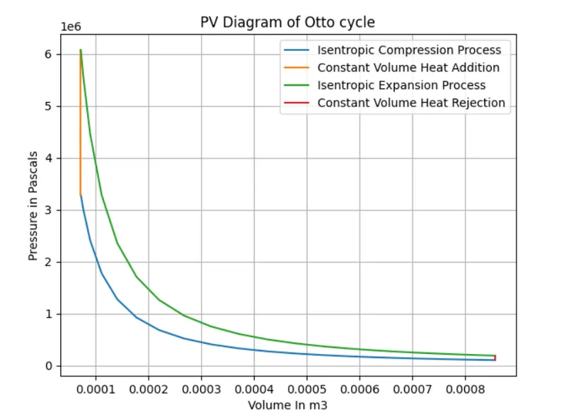
Conclusion: -
In this program we have calculated the each and every state point in PV diagram also we have plotted the same. The maximum pressure in the engine is around 60.7 Mpa and thermal efficiency of engine is around 62.98%. The thermal efficiency of otto cycle is function of compression ratio and ratio of specific heat. As specific heat is assumed to be a constant for any working fluid, the efficiency is increased by increasing the compression ratio.