Week 2 Air standard Cycle
Aim: To write code that can solve an otto cycle and make plots for it.
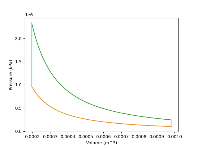
1. The code should create a PV diagram
2. Output the thermal efficiency of the engine.
Theory:
An Otto cycle (also called Constant Volume Process) is an idealized thermodynamic cycle that describes the functioning of a typical spark ignition piston engine. It is the thermodynamic cycle most commonly found in automobile engines.
The Otto cycle is a description of what happens to a mass of gas as it is subjected to changes of pressure, temperature, volume, addition of heat, and removal of heat. The mass of gas that is subjected to those changes is called the system. The system, in this case, is defined to be the fluid (gas) within the cylinder. By describing the changes that take place within the system, it will also describe in inverse, the system's effect on the environment. In the case of the Otto cycle, the effect will be to produce enough net work from the system so as to propel an automobile and its occupants in the environment.
The Otto cycle is constructed from:
- Process 0–1 a mass of air is drawn into piston/cylinder arrangement at constant pressure.
- Process 1–2 is an adiabatic (isentropic) compression of the charge as the piston moves from bottom dead center (BDC) to top dead center (TDC).
- Process 2–3 is a constant-volume heat transfer to the working gas from an external source while the piston is at top dead center. This process is intended to represent the ignition of the fuel-air mixture and the subsequent rapid burning.
- Process 3–4 is an adiabatic (isentropic) expansion (power stroke).
- Process 4–1 completes the cycle by a constant-volume process in which heat is rejected from the air while the piston is at bottom dead center.
- Process 1–0 the mass of air is released to the atmosphere in a constant pressure process.
Code:
import math
import matplotlib.pyplot as plt

def engine_kinematics(bore, stroke, con_rod, cr, start_crank, end_crank):
	#geometric parameters
	a = stroke/2
	R = con_rod/a

	#volume parameters
	V_s = math.pi*(1/4)*pow(bore,2)*stroke
	V_c = V_s/(cr-1)

	sc = math.radians(start_crank)
	ec = math.radians(end_crank)

	num_values = 50

	dtheta = (ec-sc)/(num_values-1)

	V = []

	for i in range(0,num_values):
		theta = sc + i*dtheta
		term1 = 0.5*(cr-1)
		term2 = R + 1 - math.cos(theta)
		term3 = pow(R,2) - pow(math.sin(theta),2)
		term3 = pow(term3,0.5)
		V.append((1+ term1*(term2 - term3))*V_c)

	return V

#inputs
p1 = 101325
t1 = 500

#geometric parameters
bore = 0.1
stroke = 0.1
con_rod = 0.15
cr = 5
gamma = 1.4
t3 = 2300

#volume computation
v_s = (math.pi/4)*pow(bore,2)*stroke
v_c = v_s/(cr-1)
v1 = v_c + v_s

#state point 2
v2 = v_c
p2 = p1 *pow(v1,gamma)/pow(v2,gamma)
t2 = (p2*v2)/(p1*v1/t1)
V_compression = engine_kinematics(bore, stroke, con_rod, cr, 180, 0)

constant = p1*pow(v1,gamma)

P_compression = []

for v in V_compression:
	P_compression.append(constant/pow(v,gamma))

#state point 3
v3 = v2
p3 = (t3/v3)*(p2*v2/t2)
V_expansion = engine_kinematics(bore, stroke, con_rod, cr, 0, 180)

constant = p3*pow(v3,gamma)

P_expansion = []

for v in V_expansion:
	P_expansion.append(constant/pow(v,gamma))

#state point 4
v4 = v1
p4 = p3*pow(v3,gamma)/pow(v4,gamma)
t4 = (p4*v4)/(p3*v3/t3)

#thermal efficiency
therm_eff = 1 - (1/(pow(cr,gamma-1)))
print ("Otto Cycle's Thermal efficiency: "+ str(round(therm_eff*100,2)) +"%")

plt.plot([v2,v3],[p2,p3])
plt.plot(V_compression,P_compression)
plt.plot(V_expansion,P_expansion)
plt.plot([v4,v1],[p4,p1])
plt.xlabel('Volume (m^3)')
plt.ylabel('Pressure (kPa)')
plt.savefig('Otto_cycle')
plt.show()
Explanation:
- Import math and matplotlib classes.
- Inputs taken:
- P1 = 101325 Pa
- T1 = 500 K
- T3 = 2300 K
- Bore dia = 0.1m
- Stroke length = 0.1m
- Connecting rod length = 0.15m
- Compression ratio = 5
- Gamma = 1.4
- Create a new funtion called engine_kinematics taking bore diameter, stroke, con rod length, start crank angle and end crank angle as parameters.
- This function is created to plot a parabolic curve of both the isentropic processes that take place in the Otto cycle.
- The formula in use is:

- The initial inputs contain R = connecting rod length ÷ (stroke length x 0.5)
- The function consists of the code to represent the above stated mathematical formula using a for loop.
- sc and ec are starting and ending crank angles, respectively.
- num_values is defined for the number of iterations.
- dtheta is the increment in each iteration.
- Function will return the output as V[].
- There are 4 state points involved in this cycle.
- State point 1:
- V1 = Stroke volume + Clearance Volume (V_s + V_c)
- V_s & V_c can be calculated from the given data.
- P1 and T1 are given.
- State point 2:
- This state is reached after isentropic compression.
- V2 is an array of values calc. thru engine_kinematics function.
- It is a compression process so the starting crank angle is 180 deg and ending crank angle is 0 deg.
- P2 is also an array, calculated from V2 values using PV^(gamma)=const. eqn.
- T2 is calc. using Ideal Gas eqn (PV/T=const.)
- State point 3:
- This state is reached after an isochoric heat transfer process.
- V3 is an array of values calc. thru engine_kinematics function.
- It is a expansion process so the starting crank angle is 0 deg and ending crank angle is 180 deg.
- P3 is also an array, calculated from V3 values using PV^(gamma)=const. eqn.
- T3 is calc. using Ideal Gas eqn (PV/T=const.)
- State point 4:
- This is reached after isentropic expansion.
- V4 = V1.
- P4 is calculated from V4 value using PV^(gamma)=const. eqn.
- T4 is calc. using Ideal Gas eqn (PV/T=const.)
- Thermal Efficiency:
- Thermal efficieny of Otto cycle is given by:
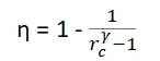
- Since the compression ratio is already given, it can be easily calculated and expressed in percentage.
- Thermal efficieny of Otto cycle is given by:
- P-V diagram is then plotted using all values avilable.
Output:
Otto Cycle's Thermal efficiency: 47.47%