Air standard Cycle
AIR STANDARD CYCLE
Aim:
To be able to write the python program to solve the otto cycle equation for creating the pv diagram and calculate the thermal efficiency of otto cycle.
Softwares required:
1.Python
2.Sublime text editor
Theory:
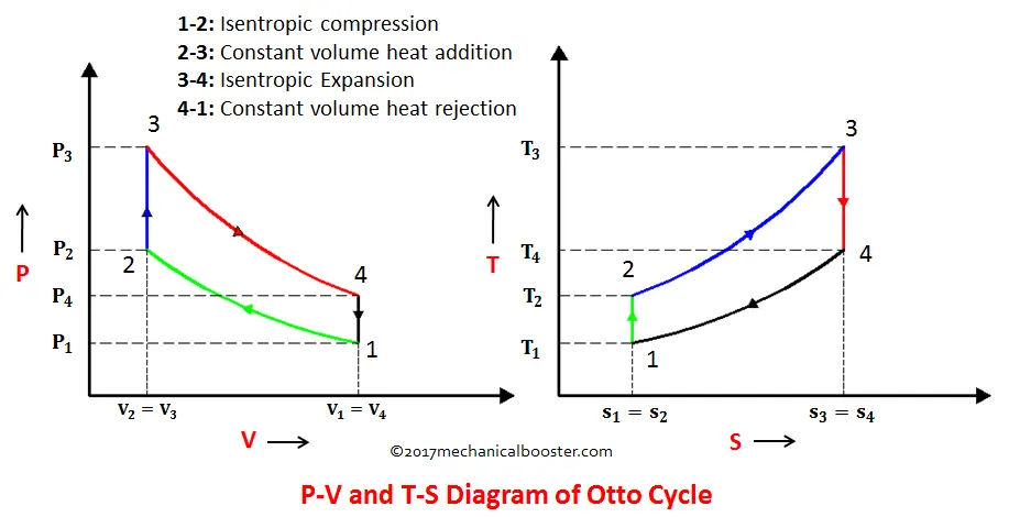
Otto cycle:
An Otto cycle is an idealized thermodynamic cycle that describes the functioning of a typical spark ignition piston engine. It is the thermodynamic cycle most commonly found in automobile engines.
The Otto cycle is a description of what happens to a mass of gas as it is subjected to changes of pressure, temperature, volume, addition of heat, and removal of heat. The mass of gas that is subjected to those changes is called the system. The system, in this case, is defined to be the fluid (gas) within the cylinder. By describing the changes that take place within the system, it will also describe in inverse, the system’s effect on the environment. In the case of the Otto cycle, the effect will be to produce enough net work from the system so as to propel an automobile and its occupants in the environment.
The Otto cycle is constructed from:
Top and bottom of the loop: a pair of quasi-parallel and isentropic processes (frictionless, adiabatic reversible).
Left and right sides of the loop: a pair of parallel isochoric processes (constant volume).
The isentropic process of compression or expansion implies that there will be no inefficiency (loss of mechanical energy), and there be no transfer of heat into or out of the system during that process. Hence the cylinder, and piston are assumed impermeable to heat during that time. Work is performed on the system during the lower isentropic compression process. Heat flows into the Otto cycle through the left pressurizing process and some of it flows back out through the right depressurizing process. The summation of the work added to the system plus the heat added minus the heat removed yields the net mechanical work generated by the system.
The idealized diagrams of a four-stroke Otto cycle Both diagrams: the intake (A) stroke is performed by an isobaric expansion, followed by an adiabatic compression (B) stroke. Through the combustion of fuel, heat is added in a constant volume (isochoric process) process, followed by an adiabatic expansion process power (C) stroke. The cycle is closed by the exhaust (D) stroke, characterized by isochoric cooling and isentropic compression processes.
Processes:
The processes are described by:
- Process 0–1 a mass of air is drawn into piston/cylinder arrangement at constant pressure.
- Process 1–2 is an adiabatic (isentropic) compression of the charge as the piston moves from bottom dead centre (BDC) to top dead centre (TDC).
- Process 2–3 is a constant-volume heat transfer to the working gas from an external source while the piston is at top dead centre. This process is intended to represent the ignition of the fuel-air mixture and the subsequent rapid burning.
- Process 3–4 is an adiabatic (isentropic) expansion (power stroke).
- Process 4–1 completes the cycle by a constant-volume process in which heat is rejected from the air while the piston is at bottom dead centre.
- Process 1–0 the mass of air is released to the atmosphere in a constant pressure process.
The Otto cycle consists of isentropic compression, heat addition at constant volume, isentropic expansion, and rejection of heat at constant volume. In the case of a four-stroke Otto cycle, technically there are two additional processes: one for the exhaust of waste heat and combustion products at constant pressure (isobaric), and one for the intake of cool oxygen-rich air also at constant pressure; however, these are often omitted in a simplified analysis. Even though those two processes are critical to the functioning of a real engine, wherein the details of heat transfer and combustion chemistry are relevant, for the simplified analysis of the thermodynamic cycle, it is more convenient to assume that all of the waste-heat is removed during a single volume change.
Processes:
The system is defined to be the mass of air that is drawn from the atmosphere into the cylinder, compressed by the piston, heated by the spark ignition of the added fuel, allowed to expand as it pushes on the piston, and finally exhausted back into the atmosphere. The mass of air is followed as its volume, pressure and temperature change during the various thermodynamic steps. As the piston is capable of moving along the cylinder, the volume of the air changes with its position in the cylinder. The compression and expansion processes induced on the gas by the movement of the piston are idealised as reversible, i.e., no useful work is lost through turbulence or friction and no heat is transferred to or from the gas during those two processes. Energy is added to the air by the combustion of fuel. Useful work is extracted by the expansion of the gas in the cylinder. After the expansion is completed in the cylinder, the remaining heat is extracted and finally the gas is exhausted to the environment. Useful mechanical work is produced during the expansion process and some of that used to compress the air mass of the next cycle. The useful mechanical work produced minus that used for the compression process is the net work gained and that can be used for propulsion or for driving other machines. Alternatively the useful work gained is the difference between the heat added and the heat removed.

Process 0–1 intake stroke (green arrow)
A mass of air (working fluid) is drawn into the cylinder, from 0 to 1, at atmospheric pressure (constant pressure) through the open intake valve, while the exhaust valve is closed during this process. The intake valve closes at point 1.
Process 1–2 compression stroke (B on diagrams)
Piston moves from crank end (BDC, bottom dead centre and maximum volume) to cylinder head end (TDC, top dead centre and minimum volume) as the working gas with initial state 1 is compressed isentropically to state point 2, through compression ratio (V1/V2). Mechanically this is the isentropic compression of the air/fuel mixture in the cylinder, also known as the compression stroke. This isentropic process assumes that no mechanical energy is lost due to friction and no heat is transferred to or from the gas, hence the process is reversible. The compression process requires that mechanical work be added to the working gas. Generally the compression ratio is around 9–10:1 (V1:V2) for a typical engine.[6]
Process 2–3 ignition phase (C on diagrams)
The piston is momentarily at rest at TDC. During this instant, which is known as the ignition phase, the air/fuel mixture remains in a small volume at the top of the compression stroke. Heat is added to the working fluid by the combustion of the injected fuel, with the volume essentially being held constant. The pressure rises and the ratio  is called the “explosion ratio”.
Process 3–4 expansion stroke (D on diagrams)
The increased high pressure exerts a force on the piston and pushes it towards the BDC. Expansion of working fluid takes place isentropically and work is done by the system on the piston. The volume ratio  is called the “isentropic expansion ratio”. (For the Otto cycle is the same as the compression ratio
  ). Mechanically this is the expansion of the hot gaseous mixture in the cylinder known as expansion (power) stroke.
Process 4–1 idealized heat rejection (A on diagrams)
The piston is momentarily at rest at BDC. The working gas pressure drops instantaneously from point 4 to point 1 during a constant volume process as heat is removed to an idealized external sink that is brought into contact with the cylinder head. The gas has returned to state 1.
Process 1–0 exhaust stroke
The exhaust valve opens at point 1. As the piston moves from BDC (point 1) to TDC (point 0) with the exhaust valve opened, the gaseous mixture is vented to the atmosphere and the process starts anew.
Program calculations and its Explanation:
Inputs:
Pressure at state 1 (P1) =101325 Pascals
Temperature at state 1 (T1) =500 kelvin
gamma =1.4
Temperature at state 3 (T3) =2300 Kelvin
bore =0.1
Stroke =0.1
Length of connecting rod =0.5
compression ratio (cr) =8
Important formulaes:
Geomentric parameters:
a=stroke/2
R=con_rod/a
Volume parameters:
Stroke volume v_s = (π/4)*(bore)2*stroke
clerance volume v_c = v_s/(cr-1)
v1=v_s+v_s
v2=v_c
constant=P1(V1)gamma
P2(V2)gamma=P1(V1)gamma
P2* V2/T2 =P1* V1/T1
rhs=P1* V1/T1
rhs=P2* V2/T2
T2=P2*V2/rhs
V3=V2
Constant=P3*(V3)gamma
P3=rhs*t3
rhs=P2*V2/T2
V4=V1
P4=P3*(V3)gamma/(V4)gamma
T4=P4*V4*T3/P3*V3
Equation for defining the relation between the crank angle and volume in the combustion chamber (V)=Vc+(Vs/2)*(cr-1)[R+1-cos(theta)-(R2-sin2(theta)0.5]
thermal_efficiency_of_otto_cycle=1-(1/(cr(gamma-1)))
Program for plotting the pv diagram of otto cycle:
"""
Otto_cycle_simulator
by thulasi ram
"""

import math
import matplotlib.pyplot as plt
import numpy as np

def engine_kinematics(bore, stroke, con_rod, cr, start_crank, end_crank):
	"""
	   Engine Kinematics
	"""

	#Geometric parameters
	a=stroke/2
	R=con_rod/a

	#volume parameters
	v_s=math.pi*(1/4)*pow(bore,2)*stroke
	v_c=v_s/(cr-1)

	sc=math.radians(start_crank)
	ec=math.radians(end_crank)

	num_values=50

	dtheta=(ec-sc)/(num_values-1)

	v=[]

	for i in range (0, num_values):
		theta=sc+i*dtheta
		term1=0.5*(cr-1)
		term2=R+1-math.cos(theta)
		term3=pow(R,2)-pow(math.sin(theta),2)
		term3=pow(term3,0.5)

		v.append((1+term1*(term2-term3))*v_c)

	return v

#Inputs

#Pressure at state 1 in pascals
p1=101325
t1=500
gamma=1.4
t3=2300

#Geometric parameters
bore=0.1
stroke=0.1
#length of connecting rod
con_rod=0.15
#compression ration
cr=8

#volume_computation
v_s=(math.pi/4)*pow(bore,2)*stroke

print(v_s)

v_c=v_s/(cr-1)

v1=v_c+v_s

#state point 2
v2=v_c

#p2v2^gamma=p1v1^gamma
p2=p1*pow(v1,gamma)/pow(v2,gamma)
print(p2)

#Temperature at state point T2
#p2v2/t2=p1v1/t1|rhs=p1v1/t1|p2v2/t2=rhs|t2=p2v2/rhs
rhs=p1*v1/t1
t2=p2*v2/rhs

v_compression=engine_kinematics(bore, stroke, con_rod, cr, 180, 0)
constant=p1*pow(v1, gamma)

p_compression=[]

for v in v_compression:
	p_compression.append(constant/pow(v,gamma))

#state point 3
v3=v2

#Ideal gas law p3v3/t3=p2v2/t2|rhs=p2v2/t2|t3=rhs*t3/v3
rhs=p2*v2/t2
print(rhs)
p3=rhs*t3/v3

v_expansion=engine_kinematics(bore, stroke, con_rod, cr, 0, 180)
constant=p3*pow(v3,gamma)

p_expansion=[]

for v in v_expansion:
	p_expansion.append(constant/pow(v,gamma))

print(p3)
#print(p3>p2) beacause after combustion pressure should be high

#state point 4
v4=v1

#p4v4^gamma=p3v3^gamma
p4=p3*pow(v3,gamma)/pow(v4,gamma)

#p4v4/t4=rhs
t4=p4*v4*t3/p3*v3
print(t4)

plt.plot([v2,v3],[p2,p3])
plt.plot(v_compression, p_compression)
plt.plot(v_expansion, p_expansion)
plt.plot([v4,v1],[p4,p1])
plt.show()
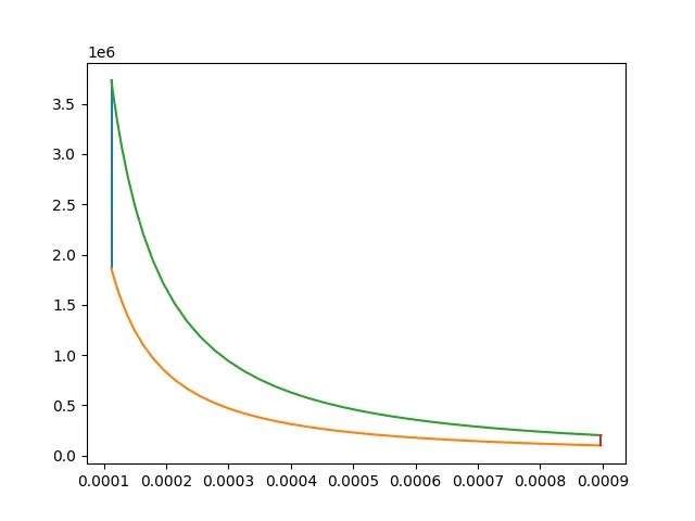
Output Pv diagram of otto cycle:
Program for calculating the efficiency of otto cycle:
"""
Thermal_Efficiency_of_Otto_Cycle
By_Thulasi_Ram
"""

import math

#Inputs required
#compression ratio
cr=8
gamma=1.4


#Formulaes yo calculate the thermal efficiency of otto cycle

#thermal_efficiency_of_otto_cycle=1-(1/cr^gamma-1))
term1=1
term2=1
term3=pow(cr,gamma-1)

thermal_efficiency=term1-(term2/term3)

print(thermal_efficiency)
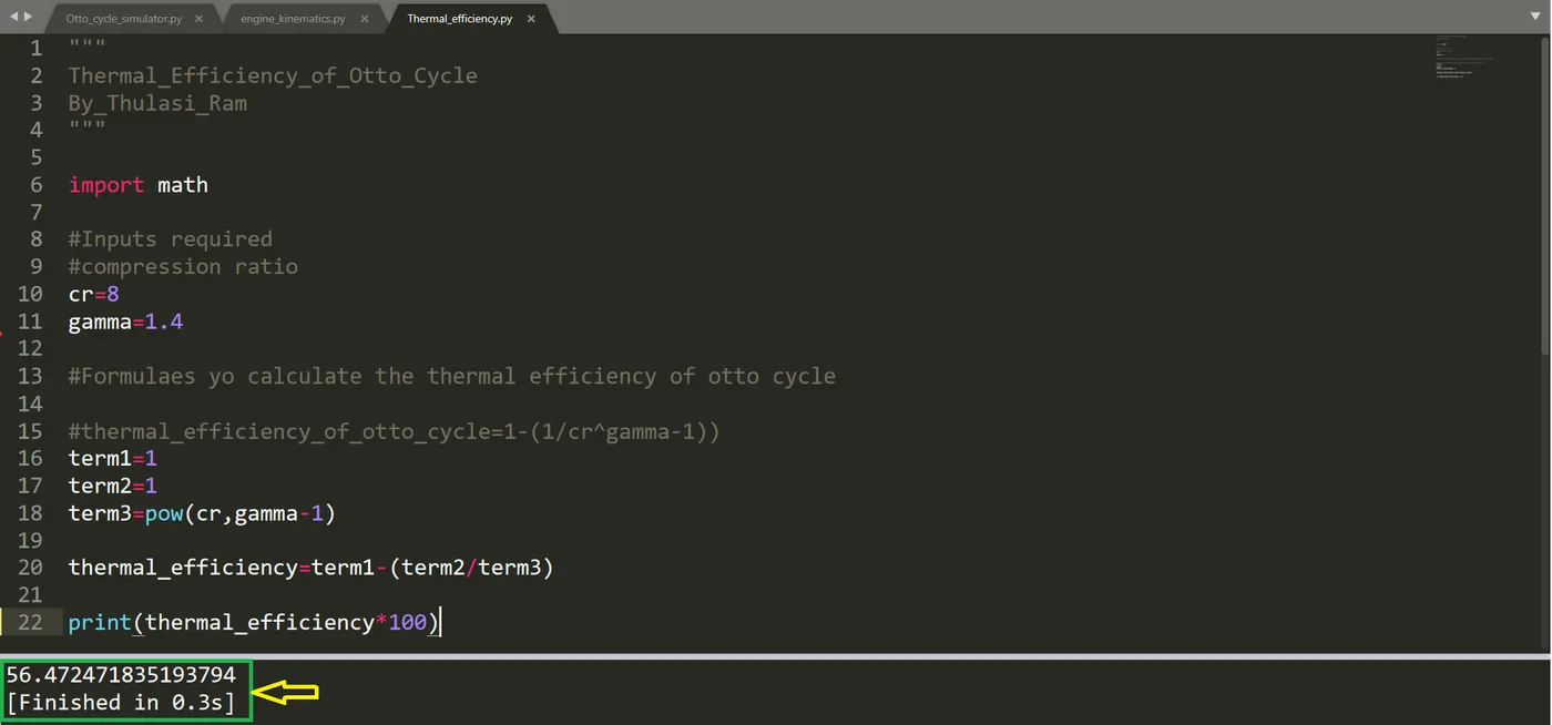
Output (sublime):
Thermal efficiency of otto cycle=56.47247%
Result:
The plotting of otto cycle pv diagram and thermal efficiency of otto cycle is calculated sucessfully.