Week 2 Air standard Cycle
Otto cycle simulator
Aim:
* To create an Otto cycle simulator for visualizing its PV Diagram and to find its efficiency.
* To find the pressure, Temperature and volume at all the four process of a four stroke engine.
Otto cycle:
* An Otto cycle is an idealized thermodyanamic cycle that describes the functioning of a typical spark ignition piston engine. It is the thermodynamic cycle most commonly found in automobile engines.
* The Otto cycle is a description of what happens to a mass of gas as it is subjected to changes of pressure, temperature, volume, addition of heat, and removal of heat. The mass of gas that is subjected to those changes is called the system.
* In the case of the Otto cycle, the effect will be to produce enough net work from the system so as to propel an automobile and its occupants in the environment.
* The otto cycle is basically a four stroke cycle where the power is generated by four step wise process.
* The process from 0 to 4 is explained below,
0 to 1 - Suction stroke:
* A mass of air (working fluid) is drawn into the cylinder, from 0 to 1, at atmospheric pressure (constant pressure) through the open intake valve, while the exhaust valve is closed during this process.
1 to 2 - Isentropic compression process:
* Piston moves from crank end (BDC, bottom dead centre and maximum volume) to cylinder head end (TDC, top dead centre and minimum volume) as the working gas with initial state 1 is compressed isentropically to state point 2, through compression ratio (V1/V2).
* Mechanically this is the isentropic compression of the air/fuel mixture in the cylinder, also known as the compression stroke.
2 to 3 - Constant volume heat addition:
* The piston is momentarily at rest at TDC. During this instant, which is known as the ignition phase, the air/fuel mixture remains in a small volume at the top of the compression stroke. Heat is added to the working fluid by the combustion of the injected fuel, with the volume essentially being held constant.
3 to 4 - Isentropic expansion process:
* The increased high pressure exerts a force on the piston and pushes it towards the BDC. Expansion of working fluid takes place isentropically and work is done by the system on the piston.
* Mechanically this is the expansion of the hot gaseous mixture in the cylinder known as expansion power stroke.
4 to 1 - Constant volume heat rejection:
* The piston is momentarily at rest at BDC. The working gas pressure drops instantaneously from point 4 to point 1 during a constant volume process as heat is removed to an idealized external sink that is brought into contact with the cylinder head. The gas has returned to state 1.
1 to 0 - Exhaust stroke:
* The exhaust valve opens at point 1. As the piston moves from "BDC" (point 1) to "TDC" (point 0) with the exhaust valve opened, the gaseous mixture is vented to the atmosphere and the process starts anew.
* Since process 1 & 3 is isentropic the entropy is constant and in process 2 & 4 the volume is made constant in an otto cycle
Procedure:
* In this project a code is written in python to simulate the above mentioned otto cycle and to find all the pressure, temperature and to calculate its efficiency.
* This coding is done with certain input parameters to estimate its efficiency and visualize its PV Diagram, and also with the logic applied in this program we can simulate several choices with change in the input parameters while doing any research in otto cycle engines.
* The program is executed firstly by specifying the ambient pressure, temperature conditions and then by providing the Engine Geometric values as the input.
* Then, the swept volume and the clearence volume is found using the engine geomentric values. Swept volume is nothing but the volume between the TDC(top dead centre) & BDC(bottom dead centre),where the piston moves up and down.
Swept volume (v_s) = (pi/4)*bore^2*stroke
* Then using the input values for engine size, the compression ratio (cr) which is the ratio of Maximum volume inside the combustion chamber to the Minimum volume inside the combustion chamber is found.
* Then we find the clearence volume, clearence volume is the tiny space available above the piston when the piston is at TDC position while on the compression process.
Clearence volume = swept volume/(cr-1)
* Then we use a formula to measure the pressure and volume change inside the engine chamber with respect to crank angle, (i.e) the formula is an mathematical equation that calculates the pressure and volume change inside the combustion chamber of the engine with respect to its change in the crank angle while rotating.
v/vc = 1 + 0.5*(cr-1) * [R + 1 - cos(theta) - (R^2 - sin(theta)^2).^0.5]
Here, (a) is the Crank pin radius = stroke/2
R - Constant to know the crank angle and piston movement = connencting rod length / a
Input Parameters:
* The input values for the engine geometry and the ambient pressure, temperature condition is specified below,
1. Gamma = 1.4
2. Ambient pressure p1 = 101325 pascal (1 atm)
3. Ambient Temperature t1 = 500 k
4. Maximum temperature after heat addition t3 = 2300 K
* Then the engine geometry specification is given below,
1. Bore (The diameter of the piston) = 0.1 m
2. Stroke (The vertical length where the piston moves) = 0.1 m
3. compression ratio (cr) = 10
4. Length of the connecting rod = 0.15 m
* Then with all of these values we can bring the pv diagram of otto cycle using the python program as below.
Python Coding:
import math
import matplotlib.pyplot as plt

# Function Program to find change of volume with repect to crank angle

def engine_kinematics(bore,stroke,con_rod,start_crank,end_crank):

	# geomentric parameters
	a=stroke/2
	R=con_rod/a

	#volume parameters
	v_s=math.pi/4*pow(bore,2)*stroke
	v_c=v_s/(cr-1)

	sc=math.radians(start_crank)
	ec=math.radians(end_crank)

	# number of theta between start & end crank
	n=50
	d_theta=(ec-sc)/(n-1)
	v=[]

	for i in range(0,n):
		theta = sc + i*d_theta

		term1=0.5*(cr-1)
		term2=R+1-math.cos(theta)
		term3=pow(R,2)-pow(math.sin(theta),2)
		term3=pow(term3,0.5)
		v.append((1+term1*(term2-term3))*v_c)
	return v

# Engine geometry inputs
bore=0.1
stroke=0.1
con_rod=0.15
cr=12

# initial pressure &temperature

p1=101325
t1=500
gamma=1.4
t3=2400

#volume calculation
v_s = math.pi/4 * pow(bore,2) * stroke
v_c = v_s/(cr-1)
v1 = v_s + v_c

#state point 2
v2 = v_c

# p2v2^gamma = p1v1^gamma
p2 = p1*pow(v1,gamma) / pow(v2,gamma)

# p2v2/t2=p1v1/t1 | rhs=p1v1/t1 | p2v2/t2 = rhs | t2 = p2v2/rhs
rhs=p1*v1/t1
t2 = p2*v2/rhs
v_compression = engine_kinematics(bore,stroke,con_rod,180,0)

constant = p1*pow(v1,gamma)
p_compression =[]

for v in v_compression:
	p_compression.append(constant/pow(v,gamma))


# state point 3
v3 = v2

# p3v3/t3=p2v2/t2 | rhs = p2v2/t2 | p3v3/t3 = rhs| p3=rhs*t3/v3
rhs = p2 * v2/t2
p3 = rhs * t3/v3

v_expansion = engine_kinematics(bore,stroke,con_rod,0,180)

constant = p3*pow(v3,gamma)
p_expansion =[]

for v in v_expansion:
	p_expansion.append(constant/pow(v,gamma))

# state point 4
v4 = v1

# p4v4^gamma = p3v3^gamma
p4 = (p3 * pow(v3,gamma))/pow(v4,gamma)

#p4v4/t4=rhs
t4 = p4 * v4/rhs

# Efiiciency of otto cycle

Efficiency = 1-((t4-t1)/(t3-t2))
print('The Efficiency of the otto cycle for the given input condition is:',Efficiency)
print('At state point 1:', 'Pressure(p1) =',p1,'; temperature(t1) =',t1,  '; volume(v1) =',v1)
print('At state point 2:', 'Pressure(p2) =',p2,'; temperature(t2) =',t2,  '; volume(v2) =',v2)
print('At state point 3:', 'Pressure(p3) =',p3,'; temperature(t3) =',t3,  '; volume(v3) =',v3)
print('At state point 4:', 'Pressure(p4) =',p4,'; temperature(t4) =',t4,  '; volume(v4) =',v4)

#plotting
plt.plot([v2,v3],[p2,p3])
plt.plot(v_compression,p_compression)
plt.plot(v_expansion,p_expansion)
plt.plot([v4,v1],[p4,p1])
plt.xlabel('volume (m^3)')
plt.ylabel('pressure(pascal)')
plt.title('PV Diagram of otto cycle')
plt.show()
* Firstly we are assingning the values for the input parameters of the first process in otto cycle,like pressure, temperature, gamma. The temperature at third process, which is the heat input given during combustion is assigned.
* Then we are giving the engine geomentric values that is the dimensions of the cylinder and some of its components in meter.
* After that we are we are calculating the swept volume ,clearence volume at volume at the 1st & 2nd process as v1 and v2.
* Since the process 1 to 2 is isentropic, we can use this expression to calculate the pressure (p2) at process 2,
p1 * v1^gamma = p2 * v2^gamma
p2 = p1 * v1^gamma / v2^gamma
*After calulation the pressure and volume at 2nd process we can find the temperature (t2) there using the Ideal gas equation which is, P.V = mr t (which is a constant ) so,
(p1 * v1) / t1 = (p2 * v2) / t2
t2 = ((p2 * v2) * t1) / (p1 * v1)
* Since the process 2 to 3 is constant volume process the volume v3 = v2. The temperature (t3) is given as the input, so with that we can calulate the pressure (p3) using the Ideal gas equation,
(p2 * v2) / t2 = (p3 * v3) / t3
p3 = ((p2 * v2) *t3) / (v3 * t2)
* Then we need to calculate the parameters at process 4. Since the process 1 & 4 is constant volume process,
v4 = v1
* As the process 3 to 4 is a isoentropic process, we use this expression to find (p4)
p3 * v3^gamma = p4 * v4^gamma
p4 = p3 * (v3/v4)^gamma
* After calulation the pressure and volume at 4th process we can find the temperature (t4), using the Ideal gas equation which is ,
p3 * v3 / t3 = p4 * v4 / t4
t4 = ((p4 * v4 )*t3) / p3*v3
* Then by knowing all the pressure temperature values at all 4 process we can plot the points using (p1 v1, p2 2, p3 v3 , p4 v4).
* But to connect the points (i.e) to trace the change in pressure and volume during the four process of an otto cycle we are using this mathematical expression, in a seperate function program.
v/vc = 1 + 0.5*(cr-1) * [R + 1 - cos(theta) - (R^2 - sin(theta)^2).^0.5]
* Where we take the inputs of bore, stroke, connecting rod length, starting crank and ending crank angle. The staring crank and eneding crank angle is converted to radians.
* Then the number of points (n), we need between stating crank angle and ending crank angle is taken as 50.
* Then the position of the crank is expressed using its momentary angle, by term d_theta, which is calculated by subtracting the current crank value with the starting crank values and dividing it by n-1
* Then we are giving the formula under a 'for loop' with the loop counting from 0 to 50, where the actual theta values which is the current angle of rotation is specified by d_theta value with respect to each iteration.
* The volume change with repect to the crank angle from (TDC to BDC) is calculated using the function program.
* To trace the change in the volume during the compression ( BDC to TDC which is 180 Degree to 0 Degree) and expansion stroke ( TDC to BDC which is 0 Degree to 180 Degree) is calculated by calling the function at the appropriate places and giving the starting crank and ending crank angle.
* To find the pressure change with repect to the crank angle, the volume change is related to the pressure change using the isentropic expression inside the for loop. The volume change is used to find the trace of the pressure change too here using the above mentioned process.
* Now the plotting is made to connect the pressure and volume points using the appropriate change in pressure and volume that we have calculated using the formula to visualize the actuall PV Diagram of the otto cycle.
* Then the efficiency of the otto cycle is calculated using the below expression,
Efficiency = work done / Amount of Heat added
work done = Amount of Heat added (t3 -t2) - Amount of Heat rejected (t4 -t1)
* Which gives the amount of heat utilized to convert it into mechanical work.
Efficiency = [(t3 - t2) - (t4 - t1)] / (t3 - t2)
* Finally the efficiency is calculated using this expreesion, Efficiency = 1-((t4-t1)/(t3-t2)).
Result:
*The python codes were done to visualize the pv diagram of a otto cycle for the given set of input parameters,
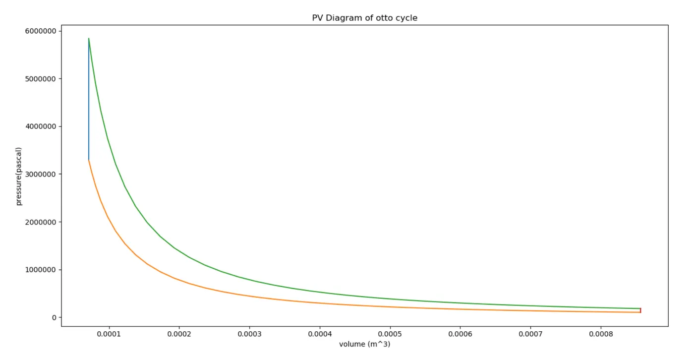
* The results are given below for the volume, temperature and pressures at all the four process,
@ state point 1:
1. t1= 500 K
2. p1 = 101325 Pascal
3. v1 =8.5680e-04 m^3
v_swept = 7.8540e-04
v_clearence =7.1400e-05
@ state point 2:
v2 =7.1399e-05 m^3
p2 = 3285264.621 Pascal
t2 = 1350.960 K
@ state point 3:
v3 = 7.1399e-05
p3 = 5836320.0
t3 = 2400 K
@ state point 4:
v4 =8.5680e-04
p4 = 180005.324
t4 = 888.257 K
* The efficiency of the otto cycle is calculated to be = 0.6298, which is 62.98 %.
* Thus the python program is coded to find the otto cycle's efficiency and also to visualize the PV Diagram of the otto cycle.
* The logic used in this python program is the base and for further studies in otto cycle engines this program can be used with the change of the input parameters as per the study, to find the efficiency and also the pressure, volume at all the four state points of an otto cycle.