Week -2
Aim -
- Make a Simulink model of Doorbell using solenoid block.
- Use a thermistor to sense the temperature of a heater & turn on or turn off the fan.
Objective -
-
To create a situation where the switch is closed for 2 seconds and then released. Observe the physical movement of the plunger.
-
To sense the temperature and to observe the following cinditions
20 °C from 0 to 10 seconds, 27 °C from 10 to 30 seconds, 23 °C from 30 to 50 seconds.
Fan conditions: ON if the temperature above 25 °C, OFF otherwise.
Theory -
1. DOORBELL using SOLENOID
The heart of a doorbell is an electromagnet. When you press a doorbell button, you complete an electrical circuit that allows electricity to flow through the doorbell's internal electromagnet. The magnetic field generated by the electromagnet is then used to power a mechanism that creates the doorbell sound.
SOLENOID
A solenoid is a long piece of wire which is wound in the shape of a coil. When the electric current passes through the coil it creates a relatively uniform magnetic field inside the coil.
Solenoids are simple components that can be used for various applications. The name solenoid is derived from the Greek word “Solen” which means a channel or a pipe. Solenoids are used in both domestic and industrial equipments, they are available in various designs, each of them has their own specific applications. Although the application changes, their working principle always remains the same.
Solenoid Working Principle
The solenoid simply works on the principle of “electromagnetism”. When the current flow through the coil magnetic field is generated in it, if you place a metal core inside the coil the magnetic lines of flux is concentrated on the core which increases the induction of the coil as compared to the air core
Most of the flux is concentrated only on the core, while some of the flux appears at the ends of the coil and a small amount of flux appears outside the coil.
The magnetic strength of the solenoid can be increased by increasing the density of the turns or by increasing the current flow in the coil.
Like all other magnets, the activated solenoid has both Positive and Negative poles, through which an object can be attracted or repelled.
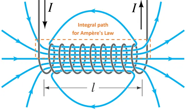
Types of Solenoids
There are different types of solenoids available in the market, the classification is made based on material, Design and function.
- AC- Laminated Solenoid
- DC- C Frame Solenoid
- DC- D Frame Solenoid
- Linear Solenoid
- Rotary Solenoid
Working of doorbell using Solenoid
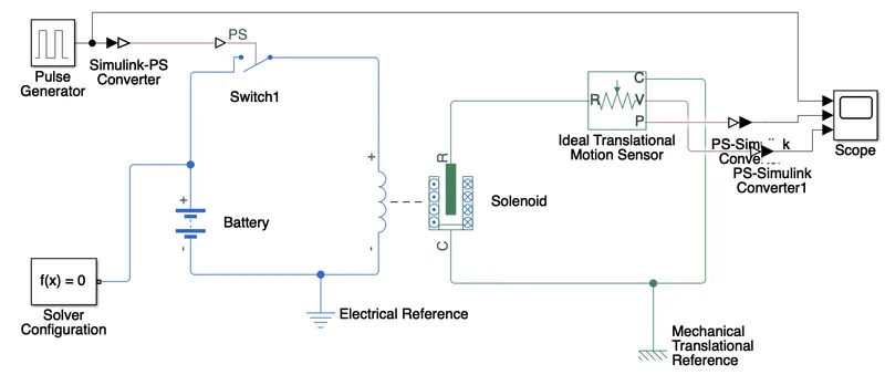
When the pulse generator genrates the voltage above the threshold voltage of the Switch, the switch will be closed and the current flows through the circuit, results generation electromagnatic field in a solenoid. The generated electromagnetic field allows plunger to move and the striker hits the bell.
While striker hits the bell, the switch gets back to its original state i.e OFF state which stops the current flow in the circuit which further causes loosing of electromagnetic field which was created in the solenoid. The plunger gets back to its original position.
SIMULINK Circuit diagram -
Pulse Generator-
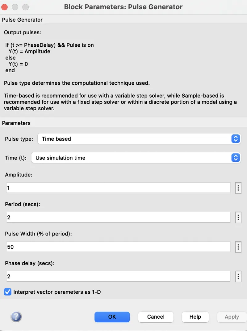
Pulse Generator generates elecrical pulses which is connected to the circuit to switch through Simulink-PS Converter.
Simulink-PS Converter block converts the unitless Simulink signal to the Physical Signal.
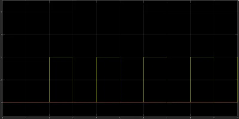
Some modifications in the pulse generator block and the generates input pulse on the scope are shown in figure bellow
One side of the switch is connected to the battery and another end of the switch is connected to the positive side of the solenoid block.
Both negative ends of the Battery and Solenoid are given to the Electrical Referance block (Ground) and Function solver block.
Solver Configuration block -
The Solver Configuration block specifies the solver parameters that your model needs before you can begin simulation. Each topologically distinct Simscape block diagram requires exactly one Solver Configuration block to be connected to it.The block has one conserving port. You can add this block anywhere on a physical network circuit by creating a branching point and connecting it to the only port of the Solver Configuration block.
When this box is selected, the solver attempts to find the steady state that would result if the inputs to the system were held constant for a sufficiently large time, starting from the initial state obtained from the initial conditions computation.
The R Port of the solenoid is connected to the ideal Transletion motion sensor to observe the movement of the plunger.
Connections R and C are mechanical translational conserving ports and connections V and P are physical signal output ports for velocity and position, respectively. The block positive direction is from port R to port C.
Physical signal output port P is connected to the scope by converting physical signal into simulink using PS-Simulink converter block.
OUTPUT -
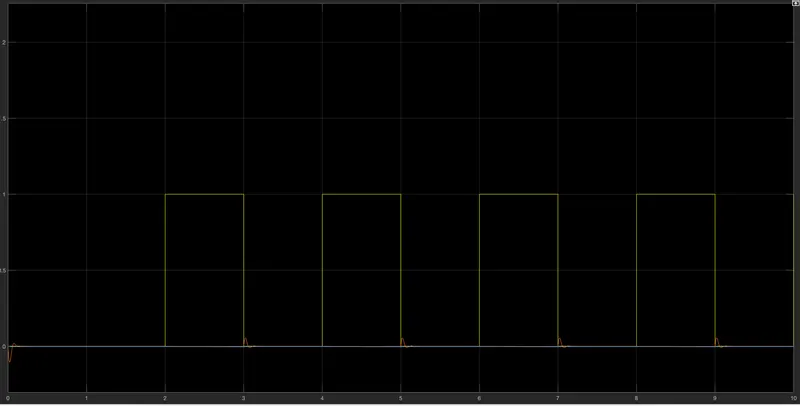
RESULT -
When the switch is closed,the electromagnetic fields are generated by the solenoid and pulls the metal arm by plunger to hit the bell which produces sound.
The motion of Plunger is observed and plotted on scope by using Ideal translation motion sesnor.
2. Thermistor
THEORY -
Thermistor Principle:
We are all known that a resistor is an electrical component that limits the amount of current flows through a circuit. Thermistor is special type of resistor, whose resistance varies more significantly with temperature than in standard resistors. Generally, the resistance increases with the temperature for most of the metals but the thermistors respond negatively i.e. the resistance of the thermistors decrease with the increase in temperature. This is the main principle behind thermistor. As the resistance of thermistors depends on the temperature, they can be connected in the electrical circuit to measure the temperature of the body.
Thermistors are mainly used as temperature sensors, inrush current limiters, self-resetting over-current protectors and self-regulating heating elements. A thermistor is made from a semiconductor material. It is shaped into a disc, a rod or a bead. Bead thermistors may be only a few millimetres in diameter. Some bead thermistors have the bead enclosed in a glass capsule.
The symbol of Thermistors can be represented as follows:
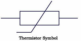
Types of Thermistors:
There are mainly 2 types of thermistors namely Positive-temperature coefficient (PTC) and Negative-temperature coefficient (NTC).
Positive Temperature Coefficient (PTC):
PTC thermistors increase their resistance as the temperature rises. The relationship between resistance and temperature is linear, as expressed in the following equation: deltaR = k(deltaT) where deltaR is the change in resistence, deltaT is the change in temperature and k is the temperature coefficient. When k is positive, it causes a linear increase in resistance as the temperature rises.
PTC Uses: PTC thermistors can be used in place of fuses for circuit protection. As the circuit heats up, resistance increases to prevent overload. They are also used as timing devices in televisions. When the unit is switched on, the degaussing coil is activated to eliminate the magnetic field; the thermistor automatically switches it off when the temperature reaches a certain point.
Negative Temperature Coefficient (NTC):
Many NTC thermistors are made from a pressed disc or cast chip of a semiconductor such as a sintered metal oxide. They work because raising the temperature of a semiconductor increases the number of electrons able to move about and carry charge – it promotes them into the conduction band. The more charge carriers that are available, the more current a material can conduct. This is described in the formula:
I = n.A.v.e
Where
I = electric current (amperes)
n = density of charge carriers (count/m³)
A = cross-sectional area of the material (m²)
v = velocity of charge carriers (m/s)
e = charge of an electron (e=1.602 \times 10^{-19} coulomb)
The current is measured using an ammeter. Over large changes in temperature, calibration is necessary. Over small changes in temperature, if the right semiconductor is used, the resistance of the material is linearly proportional to the temperature. There are many different semiconducting thermistors with a range from about 0.01 kelvin to 2,000 kelvins (-273.14 °C to 1,700 °C)
NTC Uses: NTC thermistors, on the other hand, are used as current-limiters and temperature monitors in digital thermostats and automobiles.
Simulink Circuit Model
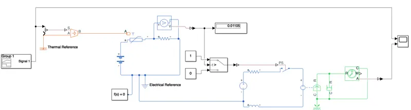
Signal input -
Input to the controlled temperature source is given by signal builder block.
Signal builder block -
The Signal Builder block allows you to create interchangeable groups of piecewise linear signal sources and use them in a model. You can quickly switch the signal groups into and out of a model to facilitate testing. In the Signal Builder window, create signals and define the output waveforms.
Signal can be created and edited manually depending on the requirment.
In the figure bellow, the signal is set to 292 kelvin i.e 20°C for 10 seconds, 300.15Kelvin i.e 27°C from 10 to 30 seconds and 298.15Kelvin i.e. 25°C from 30 to 50 seconds.
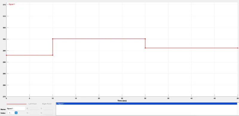
Controlled Temperature source -
This block represents an ideal energy source in a thermal network that can maintain a controlled temperature difference regardless of the heat flow rate. The temperature difference is set by the physical signal port S. A positive temperature difference causes the temperature at port B to be greater than the temperature at port A.
The output of controlled temp. source block is given to the port A of the thermistor.The positive side of the thermistor is connected to the positive side of the battery and negative side of the battery is connected to negative side of the thermistor through resistor and also connected to electrical referance and solver configuration block.
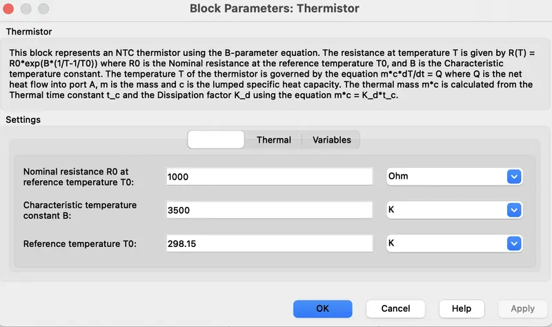
The voltmeter is connected across the resistor to check the voltage across resistor for temperature above 298.15Kelvin i.e. 25°C. This voltage value is given to the switch input as a threshold voltage. If the temperature goes above 25°C then the switch gets closed and current passes through the DC motor circuit and Fan connected to DC motor turns ON and the Fan turns OFF when temperature goes bellow 25°C.
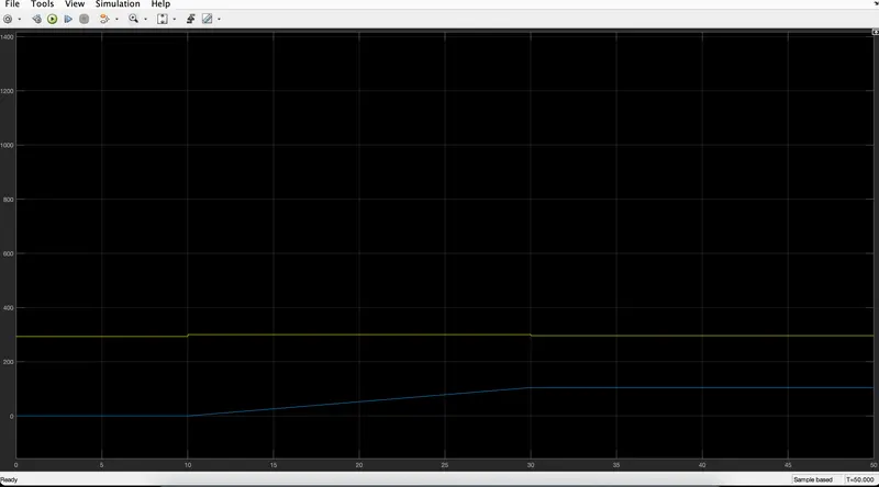
The output of the DC motor is connected to Ideal translation sensor block and the output of Ideal translation sensor block is connected to the scope by converting the physical signal into simulink singal using PS-Simulink converter block.
RESULT -
Fan is ON when temperature goes above 25°C and is OFF when temp. goes bellow 25°C.