Week -2
SIMULINK MODEL OF DOORBELL AND THERMISTOR
AIM:
- To make a simulink model of a door bell by using solenoid block.
- To use a thermistor to sense the temperature of a heater & turn on or turn off the fan as per below condition.
DOORBELL:
INTRODUCTION:A doorbell is a signaling device typically placed near a door to a building's entrance. When a visitor presses a button the bell rings inside the building, alerting the occupant to the presence of the visitor. Although the first doorbells were mechanical, activated by pulling a cord connected to a bell, modern doorbells are electric, operated by a pushbutton switch.
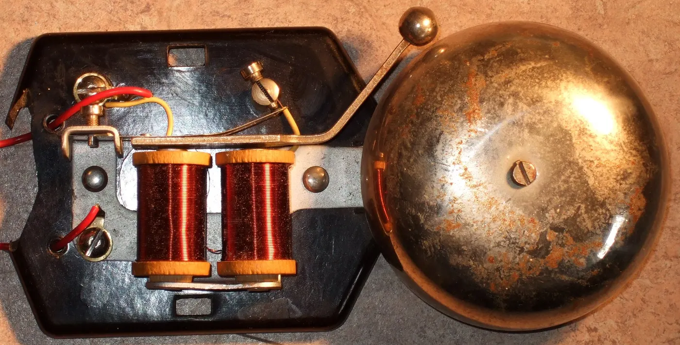
PRINCIPLE OF ELECTRIC BELL:A bell works with the principle of working of electromagnetism. When the switch is pushed on, the circuit gets completed and the current starts flowing through the U-shaped electromagnet which creates a magnetic field in the core. This attracts the iron armature.
BLOCKS USED:
PULSE GENERATOR:The pluse generator will give continous signals. It create square waves at regular time intervals.The parameters are time,amplitude,pulse time,etc.
PS-SIMULINK CONVERTER:The PS-Simulink Converter block converts a physical signal into a Simulink® output signal. Use this block to connect outputs of a Physical Network diagram to Simulink scopes or other Simulink blocks.
SCOPE:This display signals in the form of a graph
BATTERY:Battery block is a simple battery model which have positive and negative terminals.
ELECTRICAL REFERENCE:This block is used in connection to electrical ground.The Electrical Reference block represents an electrical ground
SOLENOID:A solenoid is a device comprised of a coil of wire, the housing and a moveable plunger (armature). When an electrical current is introduced, a magnetic field forms around the coil which draws the plunger in. More simply, a solenoid converts electrical energy into mechanical work.
MECHANICAL Translational REFERENCE: Reference connection for mechanical translational ports.The Mechanical Translational Reference block represents a reference point, or frame, for all mechanical translational ports
IDEAL TRANSLATION MOTION SENSOR:Motion sensor in mechanical translational systems.The Ideal Translational Motion Sensor block represents a device that converts an across variable measured between two mechanical translational nodes into a control signal proportional to velocity or position
SIMULINK-PS CONVERTER:Convert physical signal into Simulink output signal.The PS-Simulink Converter block converts a physical signal into a Simulink output signal.
SOLVER CONFIGURATION:Physical Networks environment and solver configuration.Each physical network represented by a connected Simscape block diagram requires solver settings information for simulation
CIRCUIT:
EXPLAINATION:
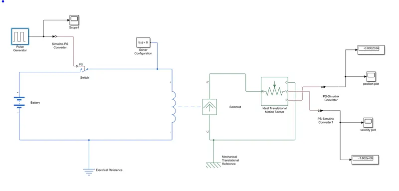
- Pulse generator which is a continous signal generator is connected to a simulink to ps converter to convert the signal into simulink language.
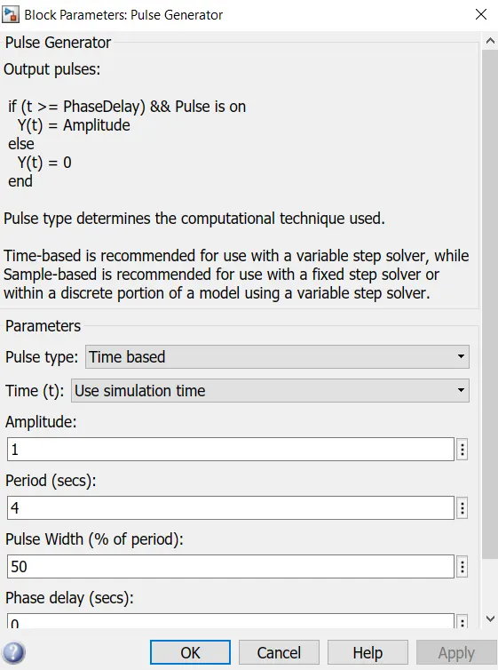
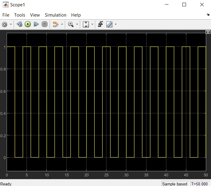
- We are required to give a input pulse which should be zero for every 2 seconds. This is obtaione dby give a time of 4 seconds and amplitude of 1 in pulse generator block.
- These pulse which are coming out of converter is connected to switch.
- Battery and electrical referance complete the following circuit.
- If the input for the switch is greater than the threshold value then the switch closes otherwise it is open.
- A solenoid is a device which converts electrical energy in to linear mechanical energy.When an electrical current is introduced, a magnetic field forms around the coil which draws the plunger in.Actually it generates a magnetic field for creating linear motion from the electric current. With the use of a magnetic field.
- To sense this translational motion which is created by the solenoid an ideal translational motion sensor is used.
- The c port of this sensor is connected to the mechanical translational reference.
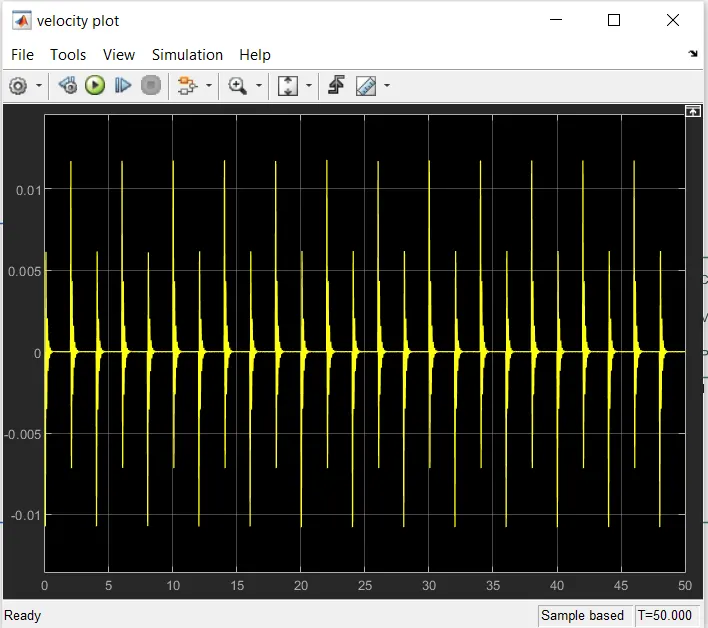
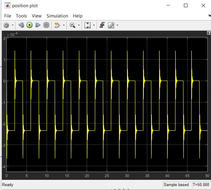
- The v port gives us the output of velocity,where as p port gives the output of position.
- This is displayed in the display block by connecting each to the velocity and position plot.
- The output of the solenoid is in simulink language we need to convert it by connecting simulink to ps converter block.
- For any output or solving in matlab we need to have a solver which is solver configuration.
OUTPUT:
PULSE GENERATOR PLOT:
VELOCITY PLOT:
POSITION PLOT:
CONCLUSION FOR DOORBELL:
The ideal run time is taken as 50 seconds. To opena and close the switch the tme taken as 2 sec.When the switch is closed the solenoid block receives electrical power from the battery and the plunger moves to hit the bell.Physical movement of plunger is sensed by the ideal translational sensor and output is displayed in the graphs.
THERMISTOR
INTRODUCTION:A thermistor is a resistance thermometer, or a resistor whose resistance is dependent on temperature. The term is a combination of “thermal” and “resistor”. It is made of metallic oxides, pressed into a bead, disk, or cylindrical shape and then encapsulated with an impermeable material such as epoxy or glass.Thermistors are used as temperature sensors. They can be found in every day appliances such as fire alarms, ovens and refrigerators. They are also used in digital thermometers and in many automotive applications to measure temperature.
BLOCKS USED:
PS-SIMULINK CONVERTER:The PS-Simulink Converter block converts a physical signal into a Simulink® output signal. Use this block to connect outputs of a Physical Network diagram to Simulink scopes or other Simulink blocks.
SIGNAL BUILDER:Create and access Signal Builder blocks.This MATLAB function returns the time (x-coordinate) and amplitude (y-coordinate) data of the Signal Builder block, block
SCOPE:This display signals in the form of a graph
CONTROLLED TEMPERATURE SOURCE:Variable source of thermal energy, characterized by temperature.The Controlled Temperature Source block represents an ideal source of thermal energy that is powerful enough to maintain specified temperature difference across the source regardless of the heat flow consumed by the system
THERMISTOR:Thermistors are used as temperature sensors. They can be found in every day appliances such as fire alarms, ovens and refrigerators. They are also used in digital thermometers and in many automotive applications to measure temperature
SIMULINK-PS CONVERTER:Convert physical signal into Simulink output signal.The PS-Simulink Converter block converts a physical signal into a Simulink output signal.
RESISTOR:A resistor is a passive two-terminal electrical component that implements electrical resistance as a circuit element. In electronic circuits, resistors are used to reduce current flow, adjust signal levels, to divide voltages, bias active elements, and terminate transmission lines, among other uses
VOLTAGE SENSOR:It is block to sense the voltage difference in the circuit
The Voltage Sensor block represents an ideal voltage sensor, that is, a device that converts voltage measured between two points of an electrical circuit into a physical signal proportional to the voltage.
Connections + and – are electrical conserving ports through which the sensor is connected to the circuit. Connection V is a physical signal port that outputs the measurement result.
SWITCH:The switch block has three ports 1,2,3. Pass through input 1 when input 2 satisfies the selected criterion; otherwise, pass through input 3. The inputs are numbered top to bottom (or left to right). The first and third input ports are data ports, and the second input port is the control port.
CIRCUIT:
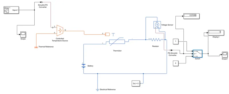
- The signal are given as per the condition in the singnal builder.
- The singnals from the signal builder are send to the controlled temperature source by converting through simulink-ps converter.
-
Controlled temperature source represents an ideal energy source in a thermal network that can maintain a controlled temperature difference regardless of the heat flow rate. The temperature difference is set by the physical signal port S. A positive temperature difference causes the temperature at port B to be greater than the temperature at port A.
- This thermal energy is send to the thermistor to sense the heat.
- Now in order to run the fan when the temperature reaches 20 degree celsius an external source battery is required to run the fan.
- To sense the voltage drop accross the circuit we have used the voltage sensor.This value is displayed in the display block.
- This voltage drop is used as a thershold value for the switch.
- When the temperature is more than 25 degree celsuis the fan is on otherwise it is off.
- In orer to solve the entire thing we have used a solver configuration.
- The outputs are displayed in the display blocks.
OUTPUTS:
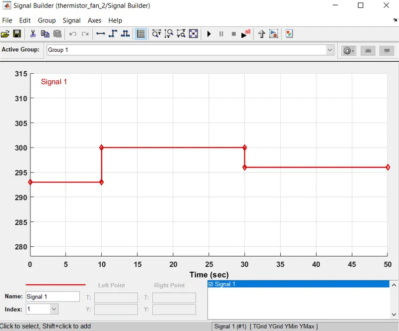
- In signal builder the values are note in the leftpoint and rightpoint.
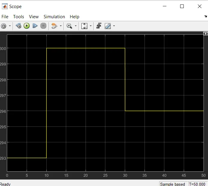
- Here the temperature values are shown according to the time specified in the condition.
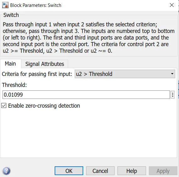
- The voltage drop accross the ciruit is 0.01099. This value is given as thershold value for the switch.
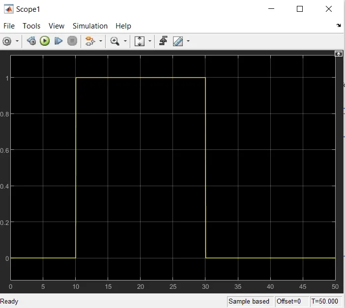
- The fan rotates when the temperature in more than 25 degree celsiuns.
- During 0 to 10 seconds the temerature value is 20 degree celsuis so fan is off. Therefore the value is zero from 0 to 10 seconds.
- During 10 to 30 seconds the temperature is 27 degree celsius so fan is on. Therefore the value is 1.
- During 30 to 50 seconds the themperature is 23 degree celsius so fan is off. Therefore the value is 0.
CONCLSION: Therefore, when the value is 0 the fan is off and when the value is 1 the fan is on. From this the thermistor model is done. The outputs gives the values of temperature and fan is in on/off condition.