Week -2
- Make a Simulink model of Doorbell using solenoid block with the following details:
In the above arrangement, when the switch is closed the electromagnet receives electrical power from the battery and pulls the metal arm to hit the bell producing sound.
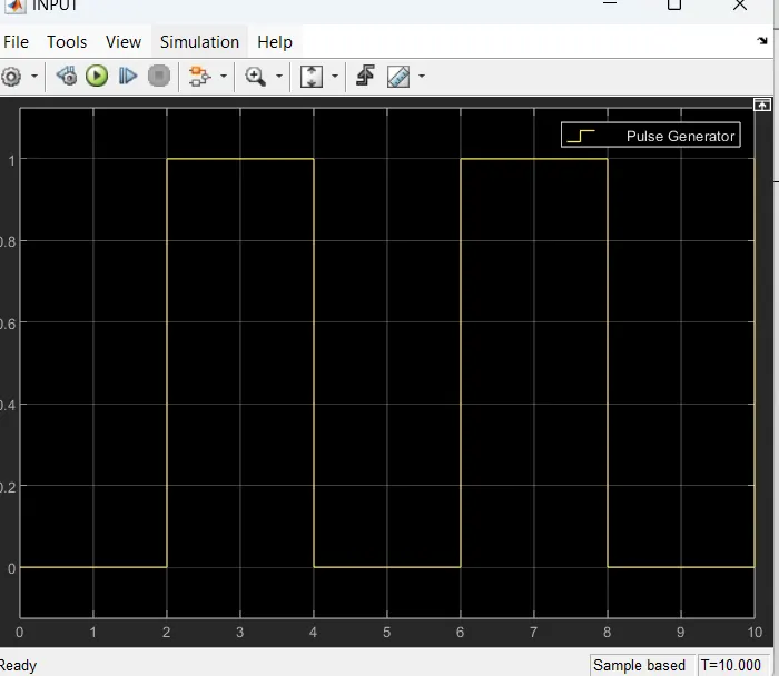
Create a situation where the switch is closed for 2 seconds and then released. Observe the physical movement of the plunger.
Assume remaining parameters.
Simulink Model :
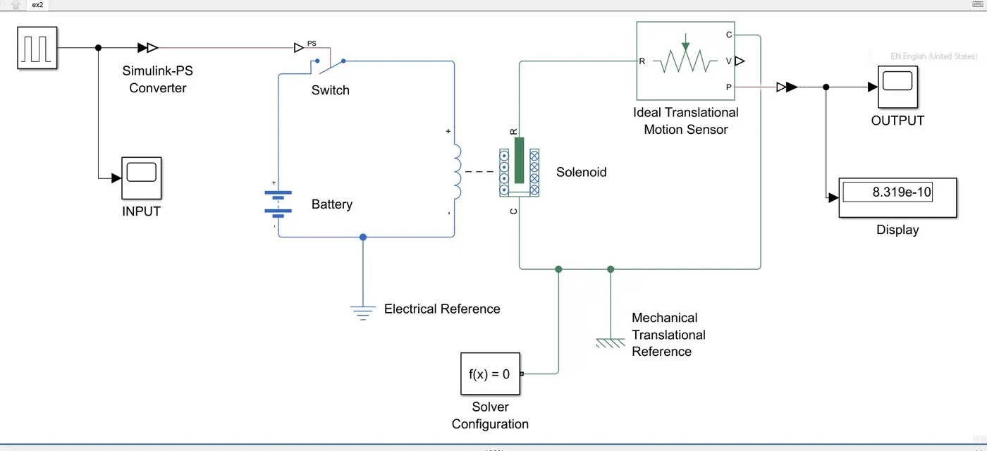
The Simulink model represents a solenoid actuator system, which is driven by a pulse input signal. The system consists of key components including a battery, switch, solenoid, and an ideal translational motion sensor. The pulse generator provides an alternating high-low voltage signal to control the switch, allowing the current to flow intermittently through the solenoid. As a result, the solenoid generates a magnetic force, which induces a linear motion in the connected mechanical system.
Pulse Generator Output :
Output :
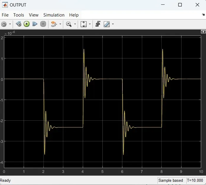
The waveform exhibits a pulsating, periodic motion with noticeable transients or oscillations at each switching event. These oscillations are due to the electromechanical response of the solenoid when the current is suddenly switched on and off. The rapid changes in current cause the solenoid’s core to vibrate slightly before settling.
===================================================================================================================================
2. Use a thermistor to sense the temperature of a heater & turn on or turn off the fan as per the below conditions:
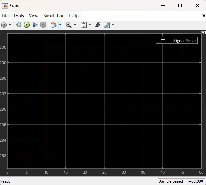
Temperature source: 20 °C from 0 to 10 seconds, 27 °C from 10 to 30 seconds, 23 °C from 30 to 50 seconds
Fan conditions: ON if the temperature above 25 °C, OFF otherwise
Simulink Model:
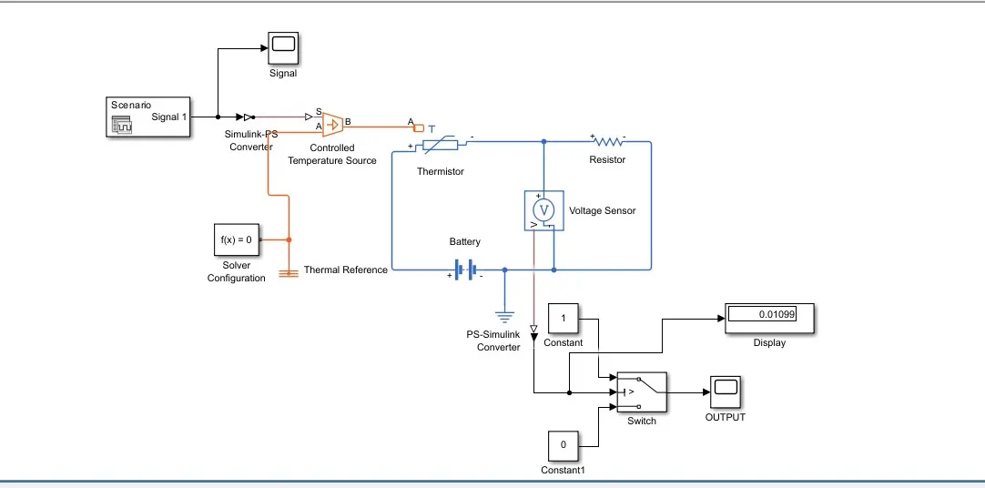
This Simulink model represents a temperature-controlled fan system using a thermistor. The Signal Editor provides a temperature profile over time, which is converted into a physical signal using the Simulink-PS Converter. The Controlled Temperature Source applies this temperature to the Thermistor, whose resistance changes accordingly. A Battery powers the circuit, and a Voltage Sensor measures the potential difference across the thermistor-resistor network. This voltage is converted back into a Simulink signal using the PS-Simulink Converter. A Switch compares this voltage with a threshold to determine if the fan should turn ON or OFF. If the temperature is above 25°C, the switch outputs 1, turning the fan ON; otherwise, it outputs 0, keeping the fan OFF. The final output is displayed on a Display block to monitor the fan status in real-time.
Input from signal editor :
OUTPUT :
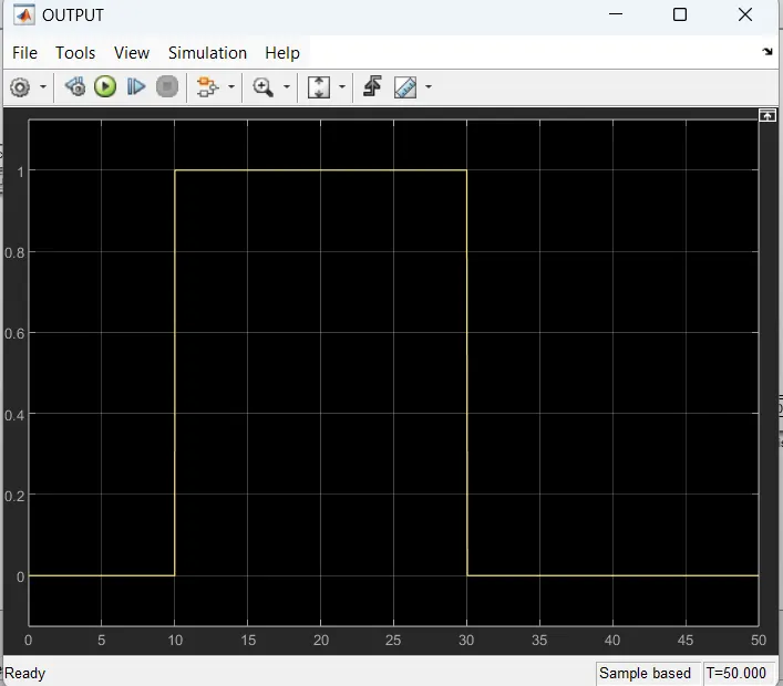
The given plot represents the ON/OFF state of the fan in response to temperature variations over time. The x-axis indicates time (in seconds), and the y-axis represents the fan state, where 1 means the fan is ON, and 0 means the fan is OFF. The fan remains off from 0 to 10 seconds as the temperature is below the threshold of 25°C. At 10 seconds, the temperature rises above 25°C, causing the fan to turn ON (1). It remains ON until 30 seconds, where the temperature drops below 25°C again, turning the fan OFF (0). The system effectively follows the predefined logic, where the fan activates only when the temperature exceeds 25°C.