Simulink Model of Doorbell using Solenoid Block and Thermistor
Objectives:
- To make a Simulink model of Doorbell using solenoid block and create a situation where the switch is closed for 2 seconds and then released.
- To make a Simulink model of Thermistor to sense the temperature of a heater & turn on or turn off the fan as per below conditions: Temperature source: 20 °C from 0 to 10 seconds, 27 °C from 10 to 30 seconds, 23 °C from 30 to 50 seconds. Fan conditions: ON if the temperature above 25 °C, OFF otherwise.
1. Simulink model of Doorbell using Solenoid
Methodology:
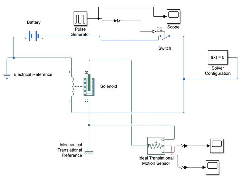
Function of block diagrams used:
Battery: The block represents a battery which act as an electric supply. It provides DC supply to the solenoid block.
Switch: The block represents a switch controlled by an external physical signal. If the external physical signal PS is greater than the threshold, then the switch is closed, otherwise the switch is open. The closed resistance is defined by parameter R_closed, and the open conductance is defined by parameter G_open. Both parameters must be greater than zero.
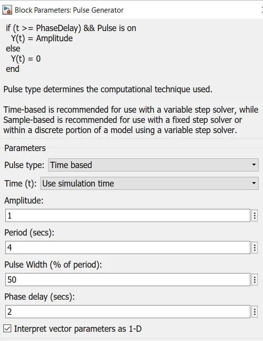
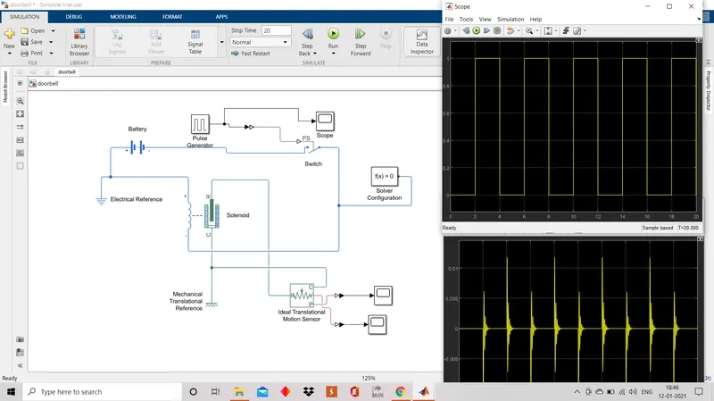
Pulse Generator: The block generates pulse type signal. It is configured as shown below and the phase delay of 2 serves the purpose of keeping the switch closed for 2 seconds.
Solenoid Block: This block implements the electrical and mechanical characteristics of a solenoid. Parameterization is in terms of two points [X1,F1] and [X2,F2] on its force-stroke curve for a 100 percent duty cycle at Rated voltage Vdc and Rated current Idc where X2>X1>0 are stroke values and F1>F2>0 are corresponding forces. The plunger fully in (i.e. air gap closed) corresponds to X=0, and pull-in force is assumed to decrease quadratically with the magnitude of X. To ensure the force remains finite, the following condition should hold: X2/X1>sqrt(F1/F2). The plunger Maximum stroke is implemented as a hard stop, the dynamics of which are set by the Contact stiffness and Contact damping parameters. The same parameters are used to model the contact dynamics when the plunger pulls fully in. The Spring constant parameter is used to implement a spring force that pulls the plunger out, and can be set to zero.
Ideal Translational Motion Sensor: This block measures velocity or displacement in a mechanical translational network. The sensor is ideal since it does not account for inertia, friction, delays, energy consumption, and so on. The physical signal ports V and P report the displacement and velocity, respectively, of port R relative to port C. The measurement is positive when the motion at R is greater than the motion at C.
Mechanical Translational Reference: This block represents a mechanical translational reference point, that is, a frame or a ground. Use it to connect mechanical translational ports that are rigidly affixed to the frame (ground).
Electrical Reference: A model must contain at least one electrical reference port (electrical ground).
Solver Configuration: Defines solver settings to use for simulation.
Explanation of the model:
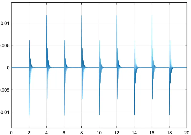
DC supply from the battery is connected to solenoid through a switch. Switch is configured with a pulse generator having a phase delay of 2sec. Switch is closed when the PS is greater than the threshold and electricity passes through the circuit. This makes the coil inside the solenoid block to produce electromagenetic induction causing the plunger to move. The motion of the plunger is detected using motion sensor and the outputs are displayed using scope. The motion of the plunger can be used to pull the metal arm to hit the bell producing sound.
Results:
Pulse Generator Output:
Y axis: Amplitude
X axis: Time(Sec)
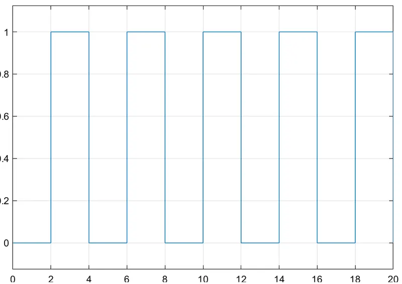
time(sec)
Plunger displacement and velocity with respect to time:
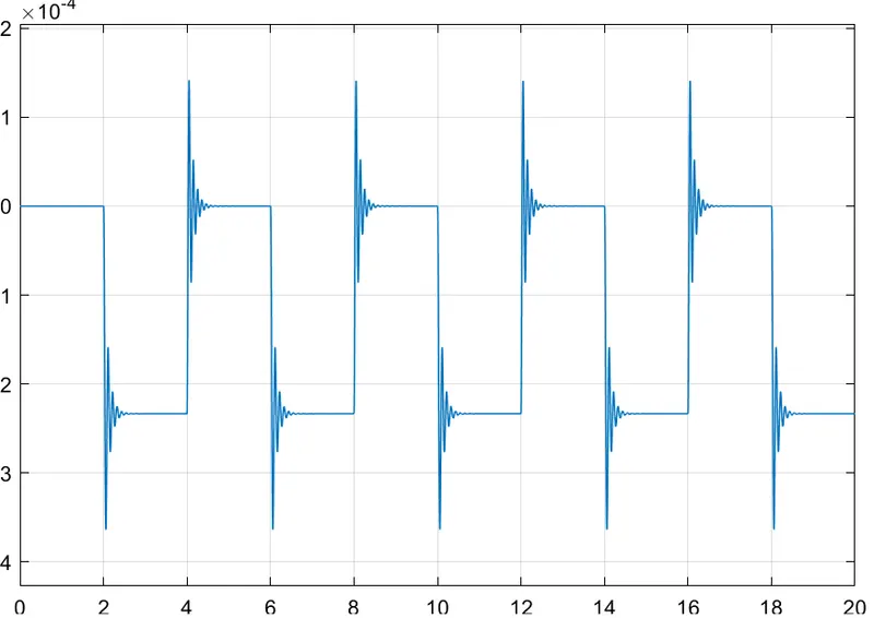
time(sec)
Screenshot of the work done:
2. Simulink model of Thermistor
Methodology:
Function of the block diagram used:
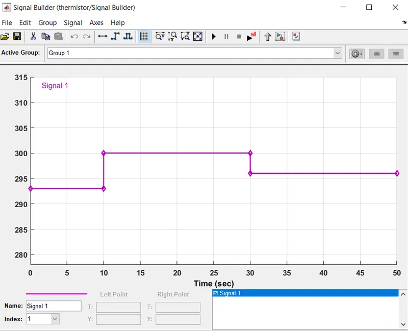
Signal Builder: A signal according to the required condition is created using Signal builder. The given temperature conditions was 20 °C (293K) from 0 to 10 seconds, 27 °C (300K) from 10 to 30 seconds, 23 °C (296K) from 30 to 50 seconds. The created signal is shown below:
Controlled Temperature Source: This block represents an ideal energy source in a thermal network that can maintain a controlled temperature difference regardless of the heat flow rate. The temperature difference is set by the physical signal port S. A positive temperature difference causes the temperature at port B to be greater than the temperature at port A.
Thermistor: This block represents an NTC thermistor using the B-parameter equation. The resistance at temperature T is given by R(T) = R0*exp(B*(1/T-1/T0)) where R0 is the Nominal resistance at the reference temperature T0, and B is the Characteristic temperature constant. The temperature T of the thermistor is governed by the equation m*c*dT/dt = Q where Q is the net heat flow into port A, m is the mass and c is the lumped specific heat capacity. The thermal mass m*c is calculated from the Thermal time constant t_c and the Dissipation factor K_d using the equation m*c = K_d*t_c.
Thermal Reference: This block represents a reference point in a thermal network where the temperature is equal to absolute zero.
Resistor: This block models a resistor with optional tolerance, operational limits, fault and thermal noise modeling. To model temperature effects, select the thermal variant of this block by right-clicking on the block and selecting Simscape block choices and Show thermal port.
Voltage Sensor: The block represents an ideal voltage sensor, that is, a device that converts voltage measured between any electrical connections into a physical signal proportional to the voltage. Connections + and - are conserving electrical ports through which the sensor is connected to the circuit. Connection V is a physical signal port that outputs voltage value.
Switch: Pass through input 1 when input 2 satisfies the selected criterion; otherwise, pass through input 3. The inputs are numbered top to bottom (or left to right). The first and third input ports are data ports, and the second input port is the control port. The criteria for control port 2 are u2 >= Threshold, u2 > Threshold or u2 ~= 0.
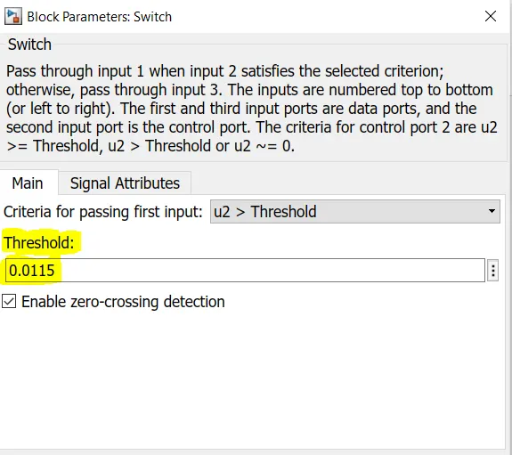
Constants: Constants with value 1 and 0 represents ON and OFF of switch respectively. If the value at the second port of the switch is greater than the threshold value, then the switch closes and the first input data of 1 is passed which makes the fan ON.
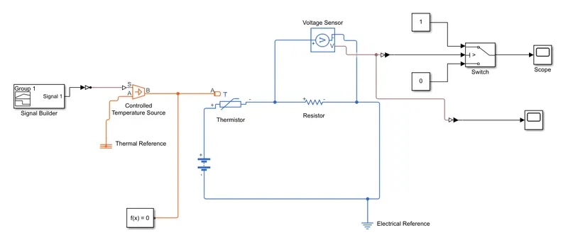
Explanation of the model:
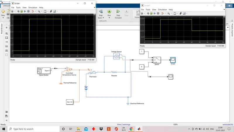
A step wise signal is created using signal builder according to the required condition and the signal is passed to the temperature source. The temperatrure source functions according to the input signal and gives theramal output to the thermistor. Thermistor is connected with a electrical circuit consists of battery, resistor and a voltage sensor. NTC Thermistors are non-linear resistors, which alter their resistance characteristics with temperature. The resistance of NTC will decrease as the temperature increases. The voltage sensor records voltage corresponding to the temperature changes. Scope connected to it displays the voltage charcterstics and the threshold voltage value (for 298K) is selected according to the plot comparing the voltage across the duration with the corresponding temperarure charcterstics defined in the signal builder. The provided switch controls the ON(1) and OFF(0) of fan which gets ON only when temperature exceeds 298K, that is when voltage value recieved at the second port of the switch is greater than the threshold value of 0.0115.
Results:
Voltage Characterstics according to the provided Temperature Conditions:
Y axis: Voltage
X axis: Time(sec)
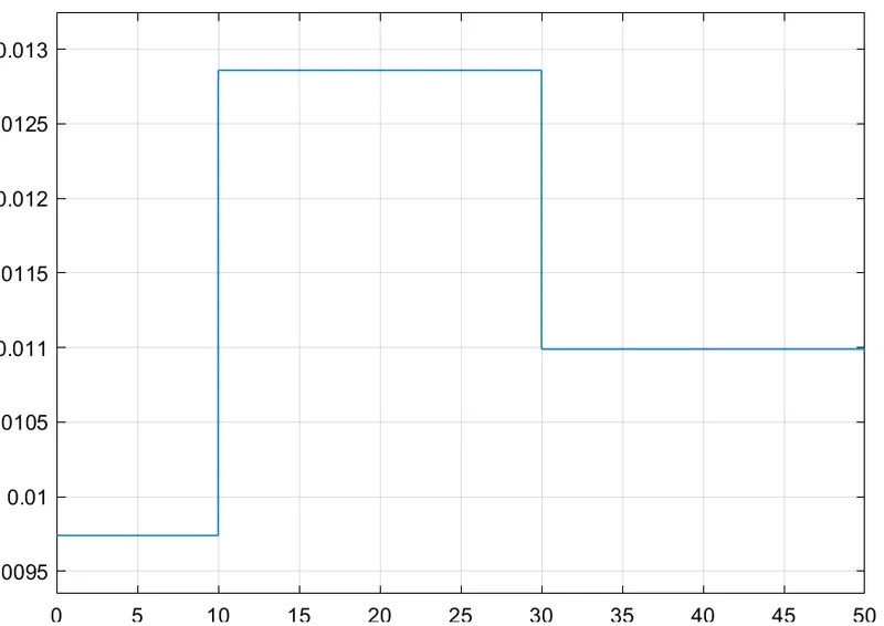
time(sec)
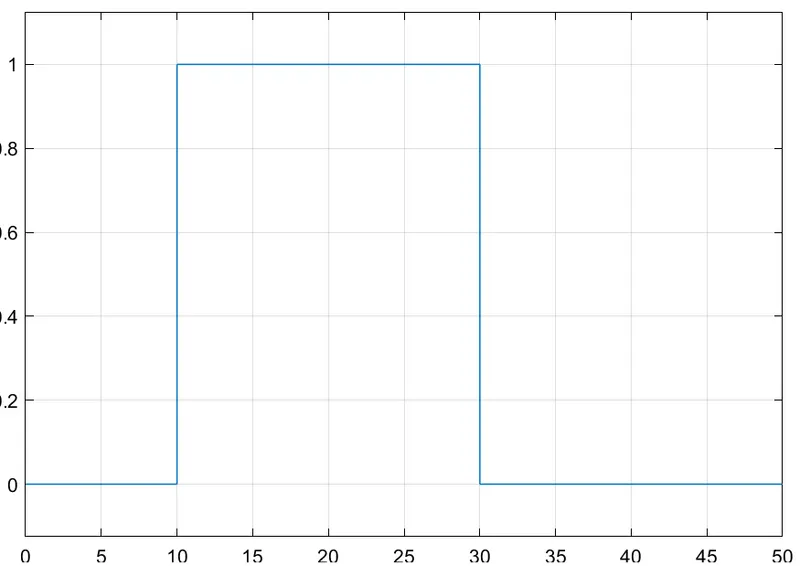
Fan ON and OFF data:
The Fan gets ON only during 10 to 30 secs when the temperarure is at 300K
Screenshot of the work done:
Links
Doorbell: https://drive.google.com/file/d/1KCjL9Pg6qvYvQ5VPtTGELWfIsc4oQTeH/view?usp=sharing
Thermistor: https://drive.google.com/file/d/1gHBxTQ5QwFe2HPq3u5YU0JbgT6Pg2pfJ/view?usp=sharing