Week -2
AIM:
Make a simulink model of doorbell and thermistor fan system
Objective
1. Make a simulink model of doorbell using solenoid block and observe the movement of plunger when switch is closed for two seconds
2. Use a thermistor to sense the temperature of a heater and turn on or turn off as per below conditions
Temperature source: 20 C from 0 to 10 seconds, 27 C from 10 to 30 seconds, 23 C from 30 to 50 seconds
Fan condition: ON if the temperature is above 25 C, OFF otherwise
1. Model
A simplied representation of doorbell is given below
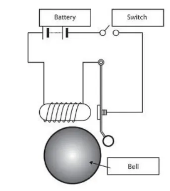
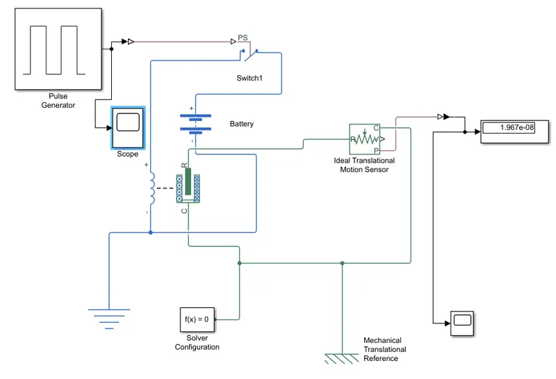
Our primary objective is to give a signal to the solenoid block for two seconds. So the required input is given using Pulse generator block. We can customize the
signal using this. An ideal translational motion sensor is used to observe the equivalent plunger movement. Arrangement of doorbell model is given below.
Results
As we customised, the output from pulse generator is given below.
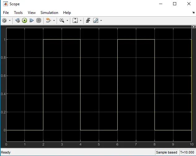
Signal makes the switch closed in the circuit for two seconds.
A scope block as arranged to the ideal translational motion sensor to observe the position of plunger.
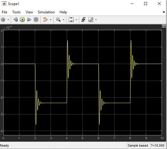
From the plot, we can observe that the plunger got excited due to the electromagnet. After two second it returned to its initial position after some vibrations.
We can control that also by providing more damping values.
2. Model
Representaion of an automatic dc fan controller is given below.
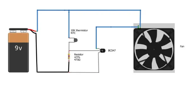
We want to simulate this type of a thermistor fan controller in simulink. For the automatic controlling, we are provided with some temperature conditions. That is, 20 C from 0 to 10 seconds, 27 C from 10 to 30 seconds, 23 C from 30 to 50 seconds and fan should ON if the temperature is above 25 C, OFF otherwise.
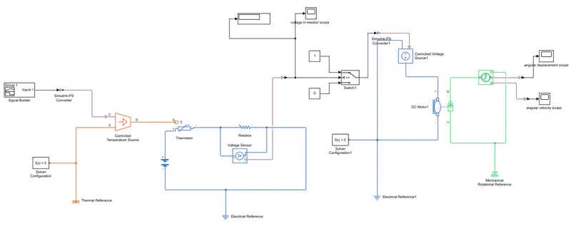
Simulink model for this is given below.
THEORY
Thermistor is a device which measures temperature, its working is based on the relationship between resistance and temperature. Here in simulink the thermistor block which is available is a positive temperature co-ecient thermistor, so here resistance of this thermistor increases or decreases with respect to temperature. The output from a thermistor is actually in the form of Voltage or Current, the increase in Voltage or Current indicates an increase in temperature.
Results
This signal is given to a controlled temperature source. It will create temperatures according to our condition. That output is given to a termistor. A resistor is connected serially to thermistor and a voltage sensor is connected to that resistance parallel. By this we will obtain the variation of voltage according to the
change of temperature. Output can be observed from a scope block which is connected to voltage sensor. The result is given below.
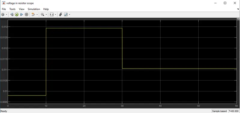
This input is given to a switch which will control our dc fan. We have a condition that, fan should on when temperature is above 25 C and off otherwise. So this condition is given to this switch by providing 0 and 1 as constant. Condition is again specified in switch conguration by adjusting the threshold value.
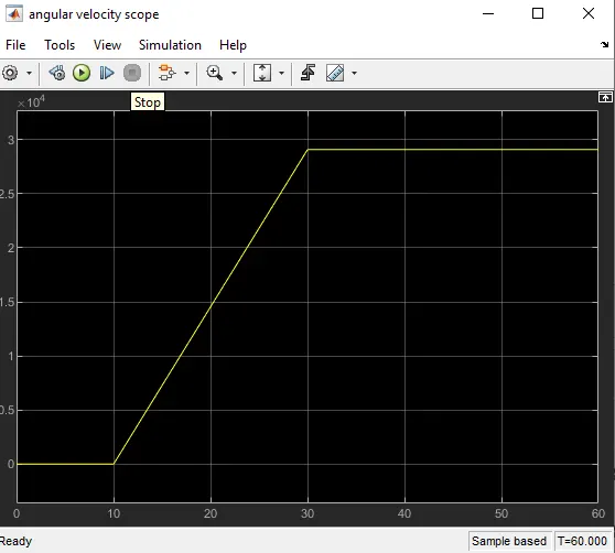
Output of the switch is given to a controlled voltage source which will provide enough voltage to the fan according to our input conditions. An ideal rotational motion sensor is connected to the dc motor to observe the motion of the fan. Motion is plotted and displayed in the scope block. It is given below.
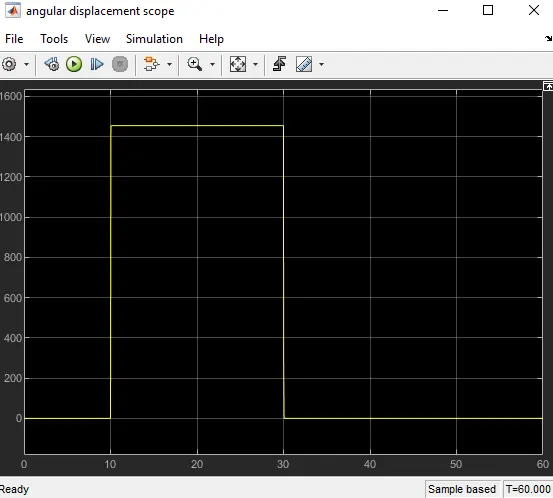
As we can see, from 10 to 30 seconds the fan got on and in other situation it remained off.
OUTPUT PLOT OF ANGULAR VELOCITY RECORDED BY THE IDEAL ROTATIONAL MOTION SENSOR
Conclusion
Simulation for a doorbell was made and the plunger motion were plotted. Automatic thermistor control for dc fan created.