Week -2
Q1.
Aim: To make simulink model for a Doorbell using solenoid block.
Objective:
- Whenever the switch is closed the electromagnet receives electrical power from the battery and pull the metal arm to hit the bell producing sound.
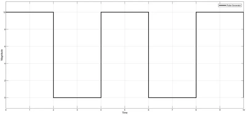
- Create a situation where the switch is closed for 2 seconds and then released. observe the physical movement of the plunger.
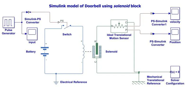
Simulink Block Model: A simulink model of Doorbell using Solenoid block is shown below.
Simulink Blocks:
- Pulse generator
- Switch
- Battery
- Solenoid
- Ideal translational motor sensor.
- Mechanical translational reference.
- Electrical reference.
- Scope
Theory:
- The pulse generator is used to create square wave pulses at regular interval. the block waveform parameters amplitude, pulse width, time period, and phase delay, determine the shape of the output waveform.
- The switch block is controlled by external physical signal. If the external signal is greater than the threshold parameter then the switch is closed, otherwise switch is open.
- The positive terminal of the switch is connected to switch and the negative terminal is connected to electrical reference.
- The solenoid block is connected with switch and battery and we will get a complete electrical circuit . The port C is connected with mechanical reference.
- The ideal translational sensor is connected with solenoid block R to observe the movement of the plunger.
- Scope is connected with the ideal translational sensor to get the output.
- PS-Simulink converter is used to convert the physical signal to simulink signal.
- Solver configuration: Each physical network represented by a connected simscape blocks require solver setting information for simulation.
Input Parameters:
|
Parameter |
Value |
|
Pulse Amplitude Time period Pulse width Simulation time Battery voltage Spring Constant of Solenoid |
10 4 sec 50% (2 sec) 10 sec 48v 100,400 |
#1 Simulation Results :
-
Pulse Generator Input:
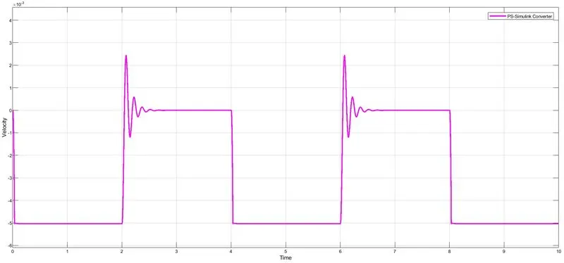
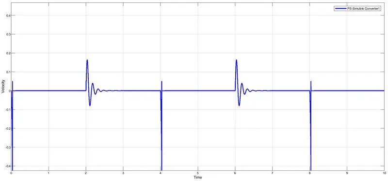
Here switch is closed for t = 0 to 2sec, and open for t= 2 to 4 sec with time period of T= 4sec by pulse generator. By giving spring constant =100 in solenoidal block. Then the simulation results as shown below.
- Position: Hear the ideal translational motion sensor sense the Physical Movement of the plunger as shown below.
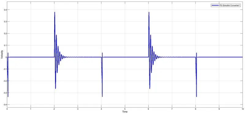
- Velocity: Hear the ideal translational motion sensor sense Magnitude of the sound did by doorbell as shown below.
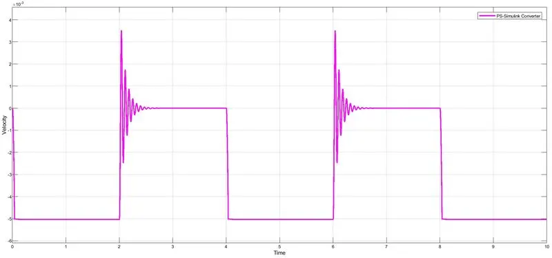
#2 Simulation Results : By giving spring constant = 400 in solenoidal block.Then the simulation results as shown below.
- Position: Hear the ideal translational motion sensor sense the Physical Movement of the plunger as shown below.
-
Velocity: Hear the ideal translational motion sensor sense Magnitude of the sound did by doorbell as shown below.
Conclusion:
From the above results conclude that if spring constant of solenoid is low then the physical movement of plunger and magnitude of sound of doorbell are low. As we increase the spring constant of solenoid then the physical movement of the plunger and magnitude of sound of doorbell are also increase.
Q2. Aim: Make a simulink block model by using a Thermistor to sense the temperature of a heater and turn on or turn off the fan.
Conditions:
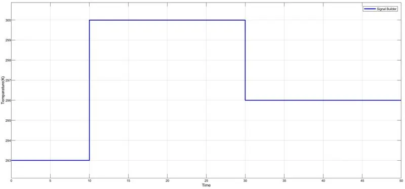
- Temperature Source: 200C (293K) from 0 to 10 Sec, 270C (300K) from 10 to 30 Sec, 230C (296K) from 30 to 50 Sec.
- Fan Conditions: ON if the temperature above 250C (298K) , OFF otherwise.
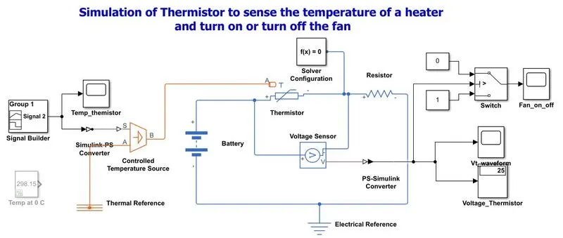
Simulink Model:
Simulink Blocks Used in Model:
- Signal Builder
- Controlled
- Temperature Source
- Battery
- NTC Thermistor
- Resistor
- Voltage Sensor
- PS-Simulink Converter
- Simulink-PS Converter
- Switch
- Thermal Reference
- Electrical Reference
- Solver Configuration
- Scope
- Display
Explanation:
- A signal builder is given as input to the NTC Themistor through a controlled temperature source with help of Simulink-PS converter.
- Battery and resistor are connected to themistor to form electrical circuit.
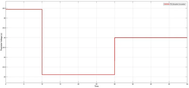
- Voltage across the NTC Thermistor measured through The Ideal Voltage Sensor block and it was display on scope with help of PS-Simulink converter.
- NTC thermistors are resistors with a negative temperature coefficient, which means that the resistance decreases with increasing temperature.
- The Sample time was taken as 10 seconds and the whole Simulation time was taken as 50 seconds.
- Firstly,by giving constant reference temperature 250C (298K) noted down the threshold value of voltage in voltage sensor i.e. Vt=23.98V which kept in the switch to turn ON or turn OFF the fan.
- Then signal builder waveforms(variable Temperature) is given to the Thermistor.
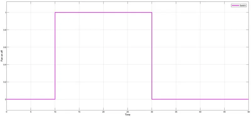
- Output of switch showed the 1(FAN ON) for above 250C (298K) and showed 0 (FAN OFF) for below 250C (298K).
Simulink Results:
-
Input Temperature :
-
Voltage across NTC Thermistor :
- Switch output:[FAN(ON/OFF)]:
Conclusion:
From the simulation outputs, for 0 to 10 Sec FAN is OFF because the temperature is 200C (293K) which is below the threshold temperature 250C (298K). After 10 Sec to 30 Sec temperature goes to 270C (300K) then FAN is ON condition as the temperature exceeds 250C (298K). After 30 Sec to 50 Sec FAN is OFF condition as the temperature come down to 230C (296K).