SIMULINK MODEL FOR WORKING OF DOORBELL AND THERMISTER
Aim
To create a situation where the switch is closed for 2 seconds and then released. Observe the physical movement of the plunger in given arrangement below.
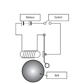
Blocks used
- Pulse generator
- Simulink –ps converter
- Battery source and switch
- Solenoid
- Ideal translational sensor
- Ps-simulink converter
- Scope
Procedure
Pulse generator : here we are required to provide a input signal which should be zero for 2 seconds and then released for 2 seconds . So we create a pulse by changing the period to 4 and pulse width to 50 by this way we can generate pulse of following pattern.
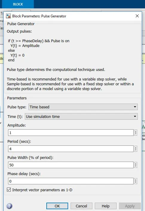
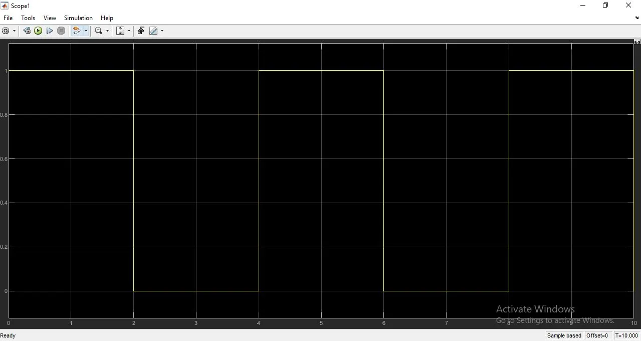
Simulink –ps converter: the signal coming from the source is converted into physical signal before giving the input to the simscape block.
Battery and switch: to supply power to the solenoid and to control the power the we can use switch. If the input is greater than the threshold then the switch is closes else the switch is in open condition.
Solenoid: a solenoid is a device comprised of a coil of wire, the housing and a moveable plunger (armature). When an electrical current is introduced, a magnetic field forms around the coil which draws the plunger in. More simply, a solenoid converts electrical energy into mechanical work. Here the plunger act as the arm of the bell.
Ideal translational motion sensor: the ideal translational motion sensor block represents a device that converts an across variable measured between two mechanical translational nodes into a control signal proportional to velocity in order to track the plunger movement we use this sensor.
Ps –simulink convertor: the ps-simulink converter block converts a physical signal into a simulink® output signal. Use this block to connect outputs of a physical network .
circuit model for doorbell:
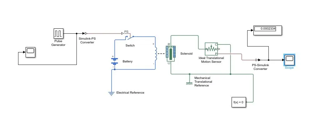
the output :
conclusion :
this is how the plunger moves with the input signal given by the pulse generator
------------------------------------------------------------------------------------------------------------------------------------------------------------------------
2. Use a thermistor to sense the temperature of a heater & turn on or turn off the fan as per below conditions:
AIM
To se a thermistor to sense the temperature of a heater & turn on or turn off the fan as per below conditions
- Temperature source: 20 °C from 0 to 10 seconds, 27 °C from 10 to 30 seconds, 23 °C from 30 to 50 seconds
- Fan conditions: ON if the temperature above 25 °C, OFF otherwise
BLOCKS USED
- signal builder
- simulink to ps converter
- controlled temperature source
- thermistor
- battery
- current sensor
- switch
- scope and display
- thermal and electrical reference
- solver configuration
- constant
PROCEDURE
signal builder : To create an interchangeable set of signal groups Drag an instance of the Signal Builder block from the Simulink Sources library and drop it into your model. By default, the block represents a single signal group containing a
single signal source that outputs a square wave pulse. here we set signal as above mentioned change the time range from 10 to 50 secondsand chnge the y axis for 0 to 10 is 293k and for 10 to 30 is 300k and for 30 to 50 is 296k as follows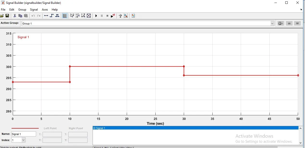
controlled temperature source : This block represents an ideal source of thermal energy that is powerful enough to maintain specified temperature difference across the source regardless of the heat flow consumed by the system
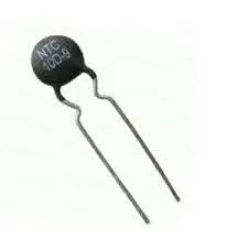
thermistor: This block represents an NTC thermistor using the B-parameter equation it has two electrical port and one thermal port represented as A and generally is defined as a thermistor is a type of resistor whose resistance is dependent on temperature,
more so than in standard resistors
battery This block is used to provide power supply to thermistor
ideal current sensor This block represents an ideal current sensor that is a device that converts current measured in any electrical branch into a physical signal proportional to the current
reference and solver configuration : Apart from this we have to connect thermal and electrical reference as well as solver configuration
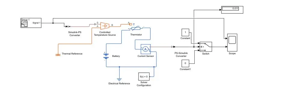
switch: Before we connect the switch with circuit we have to insert ps to simulink convertor and put the threshold value as 0.011 to auto on /off condition of fan 0.011 is the changing point for the switch or reference point to on or off condition if temperature is
above 25 fan is in on condition othervice off.
on/off condition: Now if the output is constant 1 the fan is on if the constant is 0 then the fan is off for that we have to connect two constant blocks for that with the value of 0 and 1
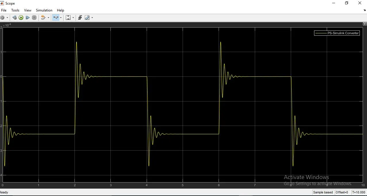
scope: this block represents the output as a graph as follows
model:
the output
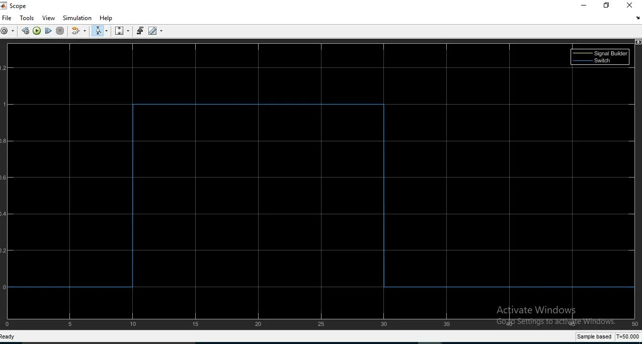
conclusion:
So we can conclude that the amplitude is 0 if temperature below 298.15 k and amplitude 1 if temp is above 298.15 k in the output graph so the above conditon mentioned was satisfied.