Week -2
Q1 simulink model of Doorbell using solenoid block :-
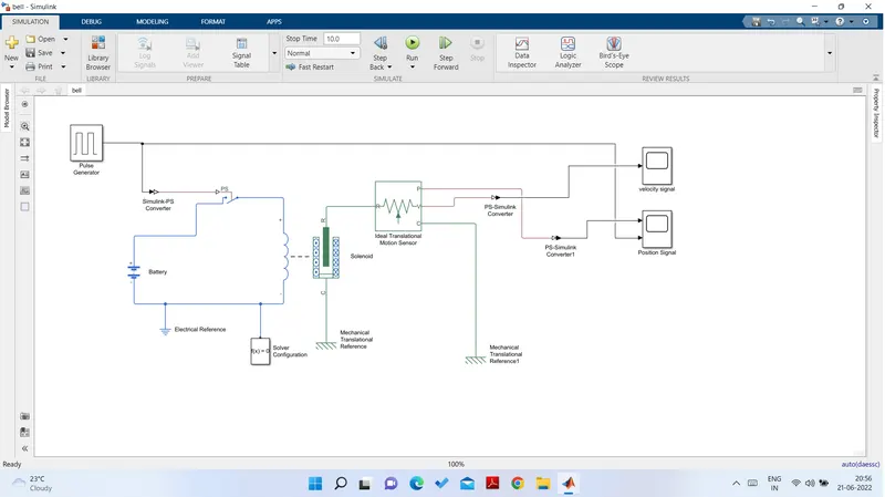
The above model uses the following blocks
- pulse Generator :-
- This block generates the pulse of amplitude 1 and for a duration of 2 Sec (50% of 4 sec) this signal is then converted to Physical Signal using the simulink-ps converter block.
- The Physical signal Controls Switch :-
The Switch remains closed if the physical signal is greater then Threshold.
In the model the blue colour circuit shownis the electrical circuit which is controlled by the Switch.When the circuit is closed the current flows from the battery to the solenoid which actuates the plunger.
- The Battery :-
The battery used in the model is 12 volts and the internal resistance is 2 ohm
- Doorbell mechanism :-
The green circuit shown in the above model is Doorbell mechanism
The plunger moves When there is a current in the solenoid.The plunger movement causes the doorbell to ring.The plunger motion is measured by a trancelational motion sensor which is plotted by the scope block.
- Solinoid :- The solinoid is the electomagnetic Device which is Activated when the electric supply given to the it.
The operation of solinoid is depends on Vdc and rated current Idc where X2,X1 are stroke values and F2,F1 are the force values the operation of plunger is depeds on stroke and force of solinoid per Duty cycle.
- Ideal trancelational Motion Sensor:-
It is the motion sensor which sence the Plunger motion to plot the plunger motion versus time.
- Results:
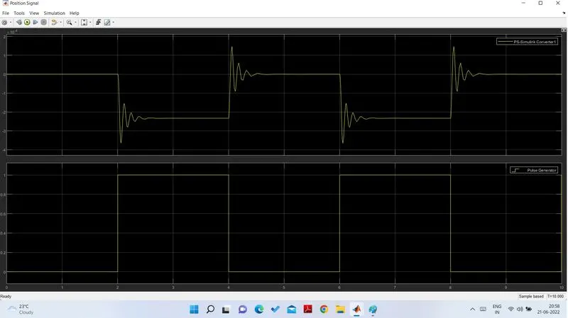
For the first 2 seconds the electrical circuit is closed and the Doorbell rings.At time =2 sec the circuit breaks and the spring pull the plunger back to its original position.Now because of the spring stiffiness the plunger oscillated for about half-a second which is nothing but damping effect.
to minimize the plunger oscillation we can increase damping coefficient of spring.
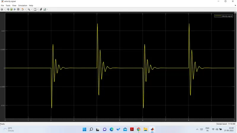
- Velocity Signal:-
Q2 Aim :- Using a thermistor to sence the temparature of a heater and turn on or off the fan when the temparature source is 20 c from 0 to 10 sec ,27 c from 10 to 30 sec , 23 c from 30 to 50 sec assumming fan condition is ON only when the temp is above 25 c.
Fan controlled by thermistor :- The thermistor is the temparature- controlled device that senses the temp and changes the resistance values accordingly.
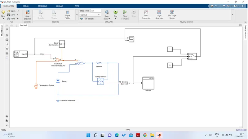
Model :-
Procedure :-
- signal builder block is used to give the input as per the given requirement given.
- A controlled temp source reperesents the ideal source of thermal energy that maintains controlled temp differences regardless of heat flow rate.
- one part of the controlled temp source is connected to the thermistor and the thermistor is connected to the resistor.
- The resistor is connected to the voltage sensor which is used to convert the voltage measured between two points into the physical signal.
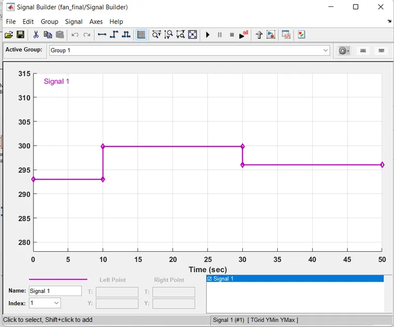
this graph indicates the signal builder where we can input our signal according to the requirement of the blocks. Here from 0 to 10 degree i have inputted the signal according to the relevant temp and the same for 10 to 30 and from 30 to 50 as well.
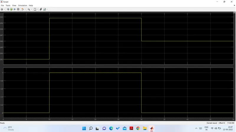
Graph 1 indicates the output from the scope where the X-axis indicates the time values from 0 to 50 sec whereas the y -axis indicates the respesctive temp in kelvin which is switch ON the fan only at the time interval of 30 to 50 when it attains the 300 kelvin (25 degree).
Graph 2 shows the output of the corresponding voltage produced across it according to the resistances values given from the thermometer.