Week -2
A Simulink model of Doorbell using solenoid block
Blocks used in model:
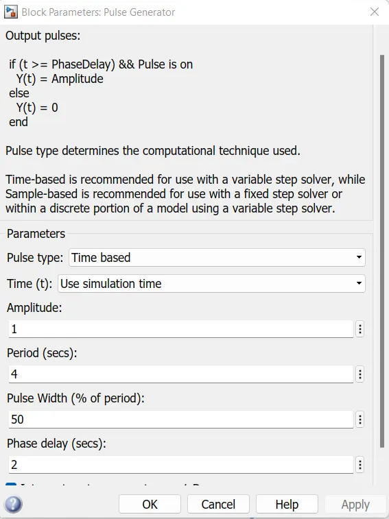
- Pulse generator The Pulse Generator block generates square wave pulses at regular intervals. The block waveform parameters, Amplitude, Pulse Width, Period, and Phase delay, determine the shape of the output waveform.
- Battery It provides voltage to the system.In Battery positive terminal is connected with switch and negative terminal is connected to "Electric Reference".
- Switch The switch Block model a switch is controlled by an external physical signal
- Solenoid Block
The Solenoid block represents the electrical characteristics and generated force for the solenoid - Ideal Translational Motion Sensor The Ideal Translational Motion Sensor block represents a device that converts an across variable measured between two mechanical translational nodes into a control signal proportional to velocity or position
- Scope To view te characterictics of a property with respect to the time(Simulation Time)
-
PS-Simulink Converter: The PS-Simulink Converter block converts a physical signal into a Simulink output signal
-
Simulink-Ps Converter This Block convert simulink signals into physical signal for operational use in Model
-
Electrical Reference Block The Electrical Reference block represents an electrical ground. Electrical conserving ports of all the blocks that are directly connected to ground must be connected to an Electrical Reference block. A model with electrical elements must contain at least one Electrical Reference block
-
Mechanical Translation Reference Block The Mechanical Rotational Reference block represents a reference point or frame for all mechanical rotational ports. All rotational ports that are rigidly clamped to the frame (ground) must be connected to a Mechanical Rotational Reference block.
-
Solver Configuration Each physical network represented by a connected Simscape block diagram requires solver settings information for simulation. The Solver Configuration block specifies the solver parameters that your model needs before you can begin simulation.
Simulink model of Doorbell using solenoid block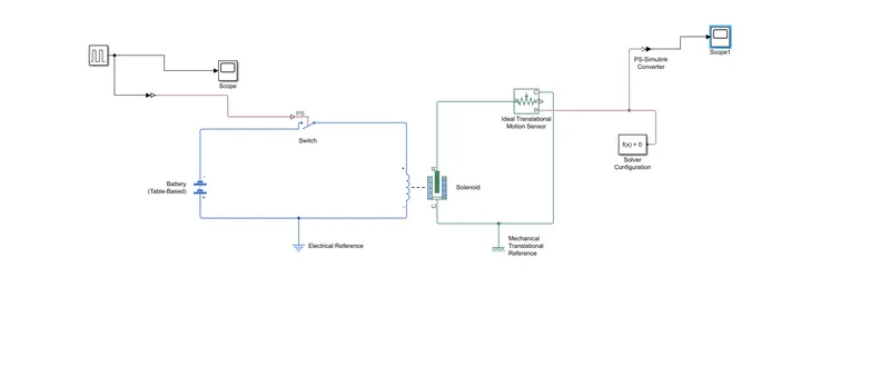
- From the given circuit of a Door Bell we know that we need a switch, solenoid, battery and a plunger. In order to get these entire component in simulink model we select the block that perform the same
- First a 'Solenoid block' is taken to represent a solenoid and then to represent battery we have taken 'Battery Block'
- Then this 'Solenoid Block' & 'Battery Block' are connected to each other via positive and negative terminals.
- A 'Switch Block' is placed between 'Solenoid Blocks' and 'Battery Block'
- Now for switch to operate we need to provide Physical signal through 'PS' port in the 'Switch Block'
- Then the whole Battery Switch and Solenoid path is connected to an 'Electric Reference Block' which represents earthing of the circuit.
- The solenoid 'R' is connected to 'R' of 'Ideal Translation Motion Sensor Block' which senses the position of plunger in the solenoid block and gives the Output
- The 'Ideal Translation Motion Sensor Block' the output are given as 'V' & 'P' which represent the velocity and position of the plunger. we are only interested in knowing the change in position of the plunger so we need only results of 'P' output
- Now 'C' in the 'Ideal Translation Motion Sensor Block' is a mechanical translation conserving port which means that the mechanical process starts from 'R' and end at 'C' and again it start at 'R' and the cycle goes on.
- So 'C' in the 'Ideal translation Motion sensor block' is connected to 'Mechanical Translation Reference' which represents a fix point where it is rigidly clamped in real time.Similarly 'C' of the solenoid block is also connected to the same 'Mechanical Translation Reference' as fixed point for solenoid.
- The position of the plunger as output from 'Ideal Translation Sensor Block' we have connected port'p' to a 'PS-Simulink Converter' and the'PS-Simulink Converter' is connected to 'Scope Block' and it will generate a graph for change in position of Plunger from port 'P' of 'Ideal Translation Motion Sensor Block'.
- Now to provide a physical signal for operating the switch, we have used a 'Pulse Generator Block' and is connected to scope so we can ge the graph
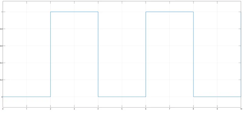
Pulse generator input
The condition was that the bell is engaged for 2 s and then released. Same was implemented by giving period as 4 seconds, pulse width as 50% and phase delay was given as 2 seconds so the simulation starts from the unengaged condition of switch.
Input signal
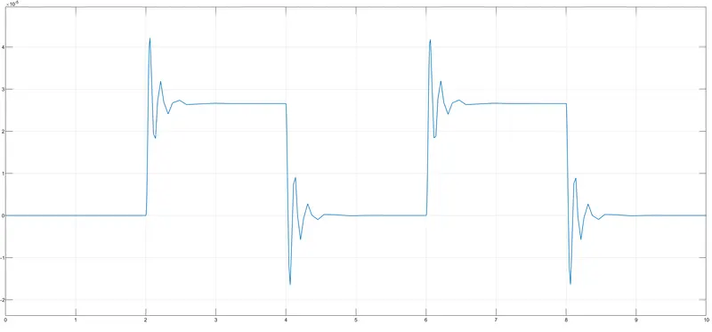
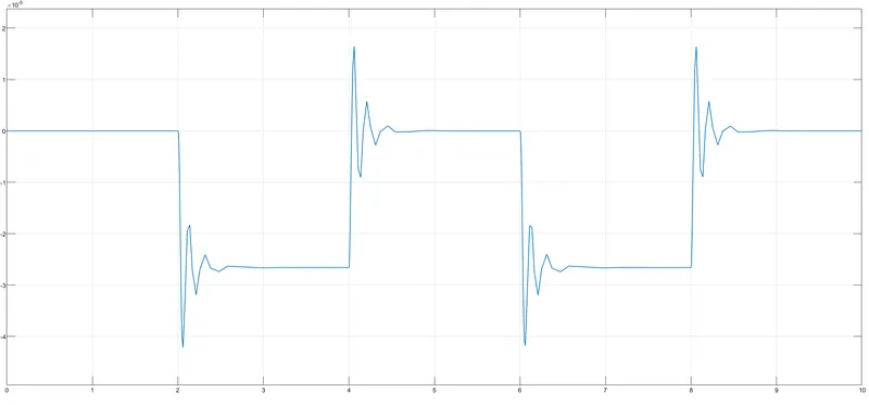
Results
The curve is positive as motion direction is set as 'port R moves away from port C'
If the solenoid parameter is set is 'port R moves toward port C' negative waveform is obtained
Conclusion
- Undesrstanding the chnges in curve characteristics upon changing the solenoid parameters
- Understanding the working principle of a doorbell and its construction
References