Week -2
Aim: This challenge aims to make a Simulink model of a doorbell using a solenoid block and make another Simulink model where a thermistor will be used to sense the temperature of a heater & turn it on or turn it off the fan.
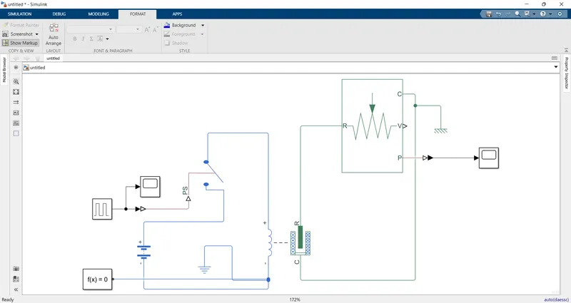
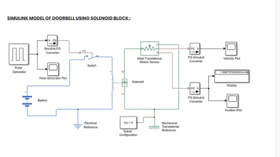
The figure above is the representation of "A doorbell operated on solenoid". In this model, some blocks are used to make the working model of the doorbell. These blocks are:
1. Pulse Generator: The Pulse Generator block generates square wave pulses at regular intervals. The block waveform parameters, Amplitude, Pulse Width, Period, and Phase delay, determine the shape of the output waveform.
2. Simulink-PS Converter: Converts the unitless Simulink input signal to a Physical Signal.
3. Scope: Display signals generated during simulation.
4. Switch: Switch controlled by an external physical signal.
5. Battery: The Battery block represents a simple battery model.
6. Solenoid: Model electrical characteristics and generated force of solenoid.
7. Ideal Translational Motion Sensor: The Ideal Translational Motion Sensor block represents a device that converts
an across variable measured between two mechanical translational nodes into a control signal proportional to velocity or position. You can specify the initial position (offset) as a block parameter. The sensor is ideal since it does not account for inertia, friction, delays, energy consumption, and so on.
8. Mechanical Translational Reference: The Mechanical Translational Reference block represents a reference point,
or frame, for all mechanical translational ports. All translational ports that are rigidly clamped to the frame (ground) must be connected to a Mechanical Translational Reference block.
9. Electrical Reference: The Electrical Reference block represents an electrical ground. Electrical conserving ports of all the blocks that are directly connected to the ground must be connected to an Electrical Reference block. A model with electrical elements must contain at least one Electrical Reference block.
10. Solver Configuration: The Solver Configuration block specifies the solver parameters that your model needs before you can begin the simulation.
11. PS-Simulink Converter: Convert physical signal into Simulink output signal..
Model Explanation:
1. The pulse generator is used to give the signal input where, Amplitude=1, Period=4 sec, Pulse width= 50%, and Phase delay= 2 sec.
2. After that, the input signal is converted into physical form with the use of "Simulink-PS Converter" and further send to the switch of the electrical circuit.
3. The electrical circuit consists of a solenoid, a battery, and a switch. One end of the solenoid is connected to the battery and its other end is connected to the switch. An electrical reference is provided in the electrical circuit.
4. The mechanical part of the solenoid is connected to an ideal translation motion sensor and mechanical translational reference.
5. The P-port of the sensor makes a connection with the "PS-Simulink Converter" to provide the output in signal form. Further, the converter is connected with scope to display our output signal.
6. A solver configuration is connected to an electrical circuit to solve all parameters before the beginning of the simulation.
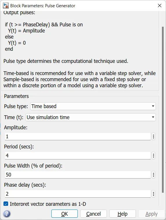
Pulse generator
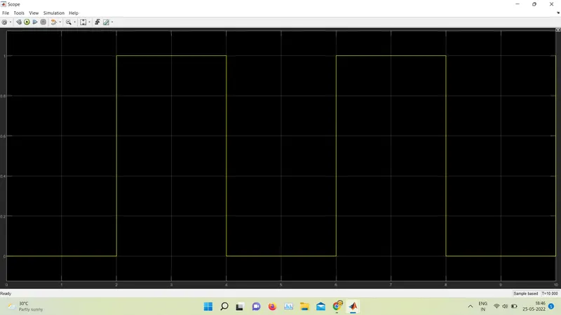
Output of solenoid valve
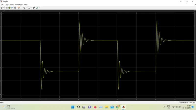
Solution of object 2
THERMISTOR:
A thermistor is a type of resistor whose resistance is strongly dependent on temperature, more so than in standard resistors. The word is a combination of thermal and resistor. Thermistors are widely used as inrush current limiters, temperature sensors (negative temperature coefficient or NTC type typically), self-resetting overcurrent protectors and self-regulating heating elements (positive temperature coefficient or PTC type typically).
Thermistors are of two opposite fundamental types:
With NTC thermistors, resistance decreases as temperature rises usually due to an increase in conduction electrons bumped up by thermal agitation from valency band. An NTC is commonly used as a temperature sensor, or in series with a circuit as an inrush current limiter.
With PTC thermistors, resistance increases as temperature rises usually due to increased thermal lattice agitations particularly those of impurities and imperfections. PTC thermistors are commonly installed in series with a circuit, and used to protect against overcurrent conditions, as resettable fuses.
OBJECTIVE:
1. To Make a Simulink model of Doorbell using solenoid block with the following details:
i. Create a situation where the switch is closed for 2 seconds and then released.
ii. Observe the physical movement of the plunger..
2. Use a thermistor to sense the temperature of a heater & turn on or turn off the fan as per below conditions:
i. Temperature source: 20 °C from 0 to 10 seconds, 27 °C from 10 to 30 seconds, 23 °C from 30 to 50 seconds. ii. Fan conditions: ON if the temperature above 25 °C, OFF otherwise.
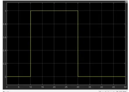
As we can see the temperature was above 25 for the time period 10-30 sec and hence we return 1 for ON for that period from the switch case. Now this signal can be given to fan input as to control it as per the temperature.