Week -2
AIM:
Make a Simulink model of a Doorbell using a solenoid block
Simulink Model:
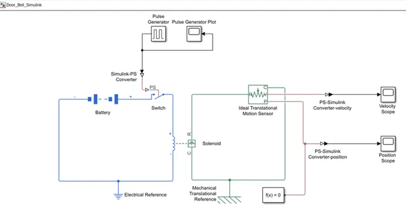
Blocks Used:
- Battery: It Provides Electrical Power Source to the System.
- Switch: The block represents a switch controlled by an external physical signal. If the external physical signal PS is greater than the threshold, then the switch is closed, otherwise, the switch is open.
- Pulse Generator: Generates a Pulsewhere the switch is closed for 2 seconds and then released.
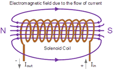
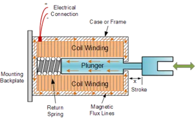
- Solenoid: A solenoid actuator can be defined as an electromagnetic device that converts an electrical signal into a magnetic field. The electrical energy is converted into a mechanical pushing or pulling force or motion. Inside the Solenoid, an electrical coil is wound around a cylindrical tube with a ferromagnetic actuator, called a plunger. When electrical current flows through the coil, a magnetic field is instantaneously generated. Thus Pulls or Pushs the Pluger depending upon the direction of the current.
- Ideal Translational Motion Sensor: The block represents an ideal mechanical translational motion sensor, that is, a device that converts an across variable measured between two mechanical translational nodes into a control signal proportional to velocity and position.
Simulink Working:
Pulse Generator Generators Pulse with 2sec interval. The Parameters to be entered on Pulse Generator are:
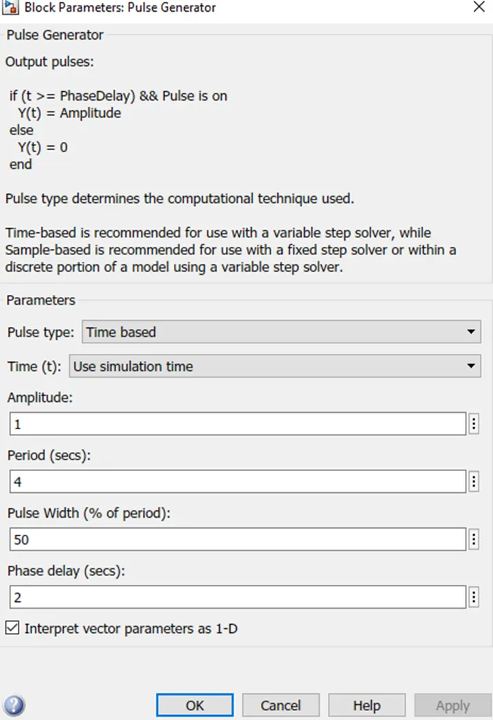
The Switch receives an external force through a pulse generator and closes the circuit for the Pulse on time.
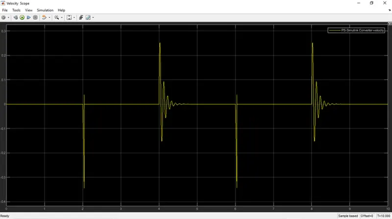
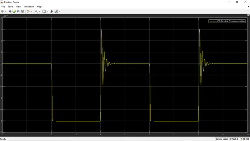
When the Switch Closes power flows through the circuit and energizes the Solenoid, thus moving the Plunger and Ringing the Doorbell for 2 secs.
Results:
Pulse Generator Plot:
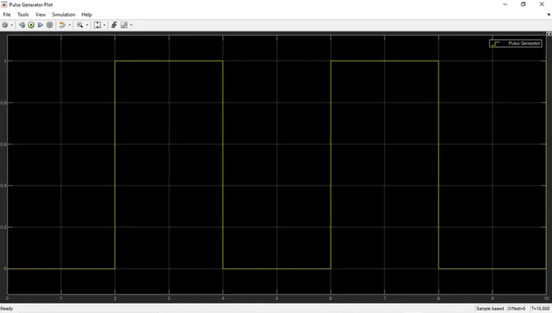
Pluse generator Output with 2-sec interval.
Solenoid - Velocity Plot:
Solenoid - Position Plot:
Conclusion:
- Simulation of Door Bell actuation at an interval of 2sec is made with the help of a pulse generator and solenoid.
- Movement of the solenoid is recorded with an Ideal Translational Motion sensor and Recorded all the Results with the Graph Plot for better understanding.
----------------------------------------------------------------------------------------------------------------
Aim:
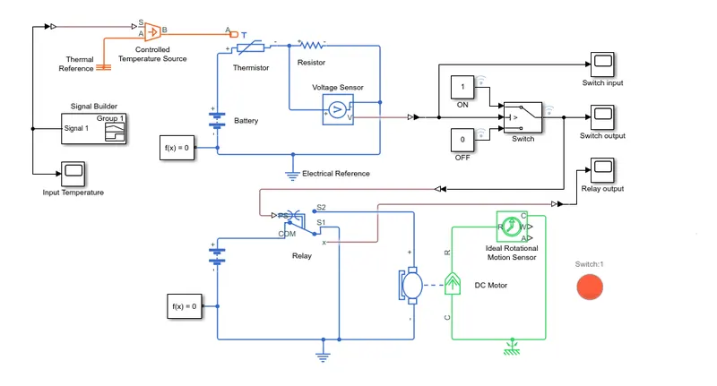
Use a thermistor to sense the temperature of a heater & turn on or turn off the fan as per the below conditions:
Temperature source: 20 °C from 0 to 10 seconds, 27 °C from 10 to 30 seconds, 23 °C from 30 to 50 seconds
Fan conditions: ON if the temperature is above 25 °C, OFF otherwise.
Simulink model:
Conditions:
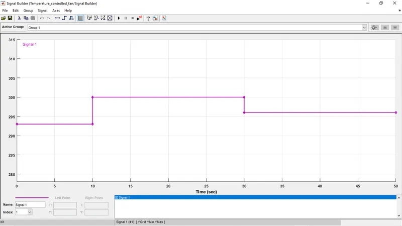
Temperature is measured in Kelvin (Equivalent conversation if Celsius).
Results:
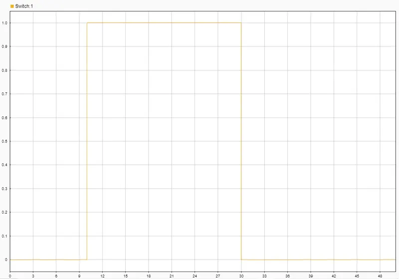 The Thermister Has a threshold setting of 298K (25 deg c), When the Temp crosses the threshold, the thermistor provides an output which inturn activates the switch.
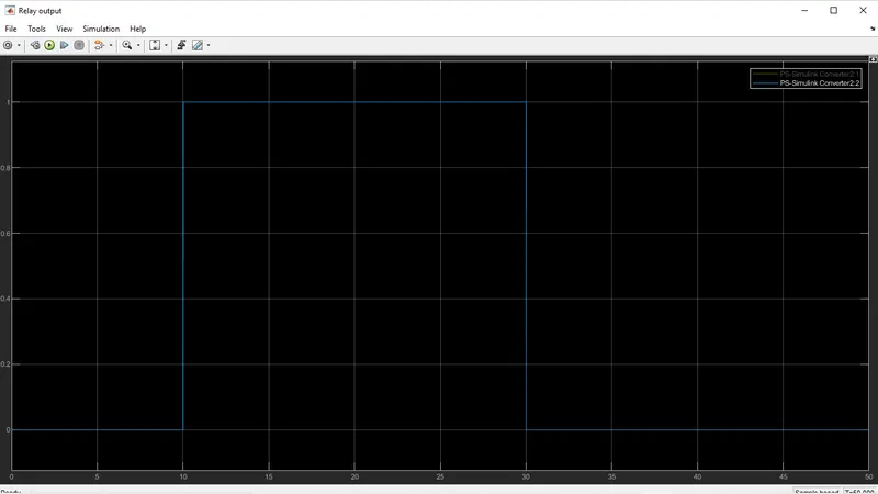 The switch Energises the relay thus the Power Flows through the battery to the DC fan. If the condition does not satisfy the output will be zero.
Thus we can see the output is energised for 10 to 30s, remaining time it was under off condition.
Conclusion:
Thermistor senses the temperature of a heater & turn on or turn off the fan as per the below conditions:
Temperature and Fan Output: 20 °C from 0 to 10 seconds - OFF, 27 °C from 10 to 30 seconds - ON, 23 °C from 30 to 50 seconds - OFF