Week 2- 2R Robotic Arm Challenge
%Forward kinematics of 2R robotic arm
clear all
close all
clc

%Inputs
l1 = 1.2;					%link one length in meters
l2 = 0.8;					%link two length in meters
theta1 = linspace(0,90,10);	%link1 10 angular positions
theta2 = linspace(0,90,10);	%link1 10 angular positions

ct=1;
for i=1:length(theta1)  %For loop to generate different positions of robotic arm
    THETA1 = theta1(i);
    for j = 1:length(theta2)
        THETA2 =theta2(j);

        %Coordinates for link one and link two
        x0 = 0;
        y0 = 0;
        x1 = l1*cosd(THETA1);
        y1 = l1*sind(THETA1);
        x2 = x1+l2*cosd(THETA2);
        y2 = y1+l2*sind(THETA2);

        %Plotting
        plot([x0 x1],[y0 y1], [x1 x2], [y1 y2], 'linewidth',3)
        axis([-0.1 1.5 0 1.5])
        pause(0.05)
        M(ct) = getframe(gcf);
        ct = ct+1;
    end
end
movie(M)
videofile = VideoWriter('forward_kinematics.avi','Uncompressed Avi');
open(videofile)
writeVideo(videofile,M)
close(videofile)
below is the link for video file
Code Explanation
Clear all - removes data from the workspace, freeing up system memory
Close all- deletes the current figure or the specified figure
clc - clears all input and output from the Command Window display, giving you a "clean screen
Next step of the code to defining the input values for leng and angles of link one & link two.
(L1)Link one length = 1.2 meter
(L2)Link two length = 0.8 meter
Theta1 = angle of link one
Theta2 = angle of link two
Here given as linspace(0,90,10) means this command generate 10 values between 0 to 90, and those values considered as 10 positions of link1 same as for link two
The next step is that for loop
for i=1:length(theta1)
THETA1 = theta1(i);
end
in that “I” is the loop counter by considering all angles it will create 1 to length(theta1) values, and same as for link two follows link one
Next will be Input entries for coordinates of link one and link two
Here, link one base coordinates will be constant because it is the fixed point of robotic arm, where the other two coordinates will be variables which generates by inputs given by using mathematical formula of a particular position.
Now plotting,
The next step is to plot the graph for the entire x and y coordinates with axis
A pause command was used for pausing the command for a certain time, for this project a pause of 0.03 s was used.
The M command was used to capture the current frame every time the for loop runs. The final step of the loop is to add a +1 to the ct variable; this will increment the frame every time the for loop run. End command was used for the plot and for the for loop to stop both from running.
Last step is making movie file
The final step of the code is to create a movie of the animation of the robotic arm, so the movie command was used.
The VideoWriter command was used to assign the video format, for this project .avi was used as the format. The open command was used to open the video. writevideo command was used to write the video with plot frames. Finally, the close command was used to
close the video file.
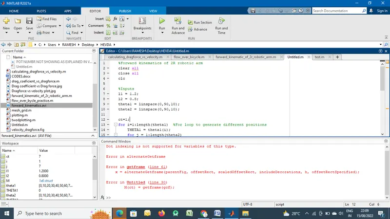
Below are the Errors while executing the code
- Error in Untitled (line 30)
M(ct) = getframe(gcf);
The above error because not defining the “ct=1;” after defined error cleared,
But for below error not clarified
Dot indexing is not supported for variables of this type.
- Error in alternateGetframe
- Error in getframe (line 61)
x = alternateGetframe(parentFig, offsetRect, scaledOffsetRect, includeDecorations, h, offsetRectSpecified);
- Error in Untitled (line 30)
M(ct) = getframe(gcf);