Week 2- 2R Robotic Arm Challenge
AIM: A MATLAB PROGRAM TO SIMULATE THE FORWARD KINEMATICS OF A 2R ROBOTIC ARM.
PREFACE: A programmable machine mainly control by the computer that can capable of performing swiftly and perfectly multiple sequence of works automatically without human labour.Studies of design,fabrication and operation discuss in Robotics.Their advance technology allows them carry on executing pace and capacity of work which is harder for human being.This type of autonomus machine extensively operate in Industrial work.Robotics has established itself in medical purpose such as replacing a damaged human body part with a robotic body part such as using a robotic arm as a substitute,helps in surgeries.Robots can be used in military.Robotic arms on spacecraft can move large objects in outer- space.Robotic spacecraft can visit other worlds.The most famous robots: the Mars rovers,like 'Perseverance' and 'curiosity' to explore Red planet as it was not possible for human.
PHYSICS BEHIND THE PROJECT: First startting in Robotics,first thing to learn about the kinematics of the linkages.It is very crucial for writing a simple program that simulate how the robot is going to move.Then we can evaluate the workspace which is possible location robot can reach.In Robotics the extent of area reachable by the robot is define by the kinematics equations to calculate the position of the end effector.It traces the path of the arm.Evaluate the x and y-distances of the robot from the origin and compare them to the values calculated by the equations for forward kinematics.These computations are performed in terms of coordinate frames.Kinematic chain is an assembly of rigid bodies connected by joints to provide motion. The number of independent movements performed by the robot wrist in three dimensional space which is basically ability of the robotic arm freely move forward,backward,up and down and to left and right.Consists all of this mechanism termed as forward kinematics.
Robotic arm designed to execute a specific task quickly,efficiently and accurately.The name 2R Robotics Arm means here 2 is the number of rotating link and R is rotation.It is a type of mechanical arm that mainly by the help of computer can be programmable with almost like a human arm.A picture of a 2R Robotic Arm is given below to understand the explanation given here.
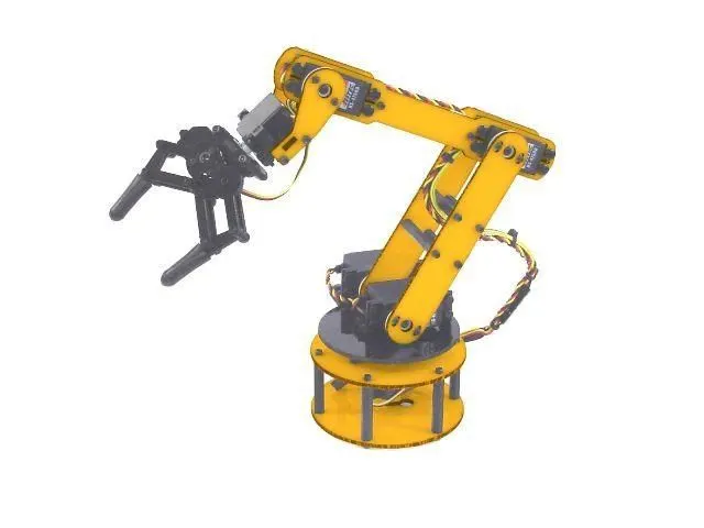
2R ROBOTIC ARM
GOVERNING EQUATION: Two links describe in the picture as `L_1` and `L_2`.First link which is `L_1` is joined at the base which origin is coordinate (X0,Y0) and making an angle theta1 with respect to the x-axis.The end coordinate of the first link is (X1,Y1).The second link show here by `L_2` which is joined at the end of the first link.second link is making an angle theta2 with respect to x-axis and the origin position of second link is (X1,Y1) and the end is (X2,Y2).
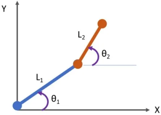
OBJECTCIVES:
- A analysis of the forward kinematics of a 2R Robotic arm which prepare a program in Matlab.
- A simulation is show here.If both of the angles are given then evaluating the final position of the manipulator.
- Make an animation of the arm and notice its behavior in different plots.
MATLAB PROGRAMMING LANGUAGE (FOR 2D PLOT ONLY)
INPUTS
% A Matlab program to plot the Forward kinematics of a 2R Robotric arm
clear all
close all
clc

% Inputs

% Variables which are used to make the plot

% Length of First link (L1),unit- meter
L1 = 1 ;

% Length of Second link (L2),unit- meter
L2 = 0.5 ;

% First link L1 is making an angle theta1,unit- degree
theta1 = 45 ;

% Second link L2 is making an angle theta2,unit- degree
theta2 = 90 ;

% Coordinate of L1 is (X0,Y0) at origin
X0 = 0 ;
Y0 = 0 ;

% Coordinate of L1 is (X1,Y1) at the end
X1 = L1*cosd(theta1) ;
Y1 = L1*sind(theta1) ;

% Coordinate of L2 at the initial point is same as the L1 at the end point

% Coordinate of L2 is (X2,Y2) at the end
X2 = X1+L2*cosd(theta2) ;
Y2 = Y1+L2*sind(theta2) ;

% Plotting
line([X0,X1],[Y0,Y1],'linewidth',3,'color','g')
line([X1,X2],[Y1,Y2],'linewidth',3,'color','y')
title('Forward kinematics of a 2R Robotic Arm')
OUTPUT
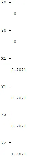
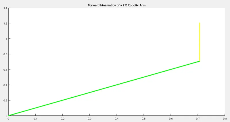
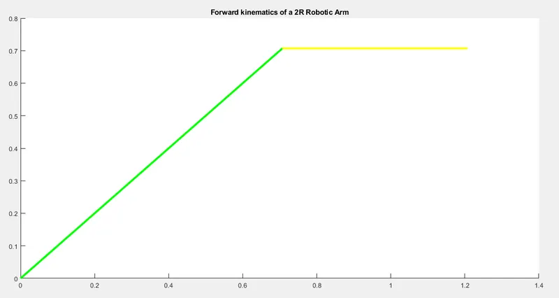
PLOT(Two link `L_1` & `L_2` of the Robotic Arm when theta2 = 90)
PLOT(Two link `L_1` & `L_2` of the Robotic Arm when theta2 = 30)
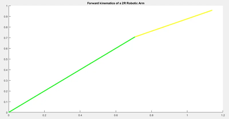
PLOT(Two link `L_1` & `L_2` of the Robotic Arm when theta2 = 0)
BRIFFING THE PROGRAM: Forward Kinematics of a 2R Robotic arm contains 2 links and 2 rotational joints.
First link `L_1` making an angle with respect to x-axis theta1 which is theta1 = 45 , in degree
Second link `L_2` making an angle with respect to y-axis theta2 = 30 , in degree
Length of the first link is `L_1`
Length of the second link is `L_2`
Starting point of first link `L_1` is fixed at the joint and ending point is connected with the second link `L_2`
First step is to calculate the position of the first link `L_1`
Coordinate of starting point of the first link `L_1` is going to be X0 = 0 , Y0 = 0
Coordinate of end point of the first link `L_1` is going to be X1 = L1*cosd(theta1) , Y1 = L1*sind(theta1), here cosd is used because it takes inputs in degree whereas cos function it takes inputs in radian. Here value is given in degree.
Second step is to calculate the position of the second link `L_2`
End point of first link `L_1` is the starting point of second link `L_2`
So the Coordinate of starting point of the second link `L_1` give here is X1 = L1*cosd(theta1), Y1 = L1*sind(theta1)
Coordinate assigned to the end manipulator of `L_2` here is X2 = X1 + L2*cosd(theta2) , Y2 = Y1 + L2*sind(theta2)
With this write a Matlab program and get a 2D plot which is showing above.
First in starting we give a comment using '%' that what the program is all about.Then we started with command close all,clear all and clc to clear all the command window,workspace variables and close all plot window.
To get the plot we giving some inputs, length of the first link `L_1` = 1 meter and length of the second link `L_2` = 0.5 meter
Now by executing the program we get the output of X1,Y1,X2,Y2
Now we visualize the Links by making a plot.
We can draw lines between the three points we have to visualize the Robotic Arm by using line command.
First we have give line command then we give the X coordinate of the two points that make up the line.In case of first link first point is origin (X0,Y0) and end point is (X1,Y1).So list of X Coordinate is given [X0,X1] followed by the list of Y coordinate [Y0,Y1].To get a thicker line we gave 'linewidth' command which value is 3 and by using 'color' command we color this line which is green 'g'.
Executing the program we got the first link `L_1` which is showing above plot for First link of the robotic arm.
For second link list of X coordinate is [X1,Y1] and Y coordinate is [X2,Y2].The yellow line is repreasent the second link `L_2` in the second picture above.
We show different position in the above picture of the manipulator by taking different angle.
Hence we plot the two link of the Robotic Arm.
CONCLUSION:
- Second link `L_2` is shorter than the first link `L_1` that is because length of the second link is `L_2` = 0.5
- The angle which `L_2` makes with respect to x-axis is lesser than what `L_1` makes because theta1 = 45 and theta2 = 30
- we can visualize differnt position of manipulator by changing the angle theta2
If theta2 = 0 degree , then second link is flat
If theta2 = 90 degree, then second link is straight upward.
For Animating the Robotic Arm: Here the objective is animate the plot.Each value of theta1 and theta2 robotic arm takes different position.We are animating it.We takes multiple values of theta1 and theta2 and for each value of theta1 and theta2, we create a plot and we stiching all these plots together to make an animation.
Previously we change the value of angles theta1 and theta2 manually the plot also change accordingly.Now we have change the values of theta1 and theta2 using program.
We give the inputs of the angle using linspace command.Asigned in the variable theta1 and theta2.Both are array.
theta1 and theta2 have 10 values between them starting from 0 to end at 90.
For each value of theta1 and theta2, we have to repeat the same calculation used in the previous program.
To change the angle we are using For-loop command.
Here length(theta1) means the number of values in theta1 which is 10.Here in for-loopThe value of i is changing from 1 to length of theta1 which is 10,each and every time it is store only one value.Each time the value change it is determine that how many times for-loop is going to executed.
As the value of i change,taking theta1 and theta2 from the original array and assign in the variables called THETA1 and THETA2.
We need to use loop counter variable ('i') here to access particular value.we use the value of i to take a particular value of theta1 and theta2 and then perform the kinematic calculation.
Each value of theta1,each position of the first link,second link can take multiple positions and it depend on theta2.So theta2 needs to use another for loop.Here the loop counter variable is ('j').
For each value of theta1 we are looping the value of theta2.We perform the forward kinematic calculation here.
MATLAB PROGRAMMING LANGUAGE (For Plotting)
% A program for different position of Arm for different values of angle
close all
clear all
clc

% Inputs

% Length of First link (L1),unit- meter
L1 = 1 ;

% Length of Second link (L2),unit- meter
L2 = 0.5 ;

% The inputs for the angle,unit- degree

theta1 = linspace(0,90,10) ;
theta2 = linspace(0,90,10) ;

% Angle changing using for loop
 for i = 1 : length(theta1)
     THETA1 = theta1(i) ;
     for j = 1 : length(theta2)
         THETA2 = theta2(j) ;

         % Coordinate of L1 is (X0,Y0) at origin
         X0 = 0 ;
         Y0 = 0 ;

         % Coordinate of L1 is (X1,Y1) at the end
         X1 = L1*cosd(THETA1) ;
         Y1 = L1*sind(THETA1) ;


         % Coordinate of L2 is (X2,Y2) at the end
         X2 = X1+L2*cosd(THETA2) ;
         Y2 = Y1+L2*sind(THETA2) ;

         % Plotting
         line([X0,X1],[Y0,Y1],'linewidth',3,'color','g')
         line([X1,X2],[Y1,Y2],'linewidth',3,'color','y')
         title('Forward kinematics of a 2R Robotic Arm')
     end
 end
PLOT
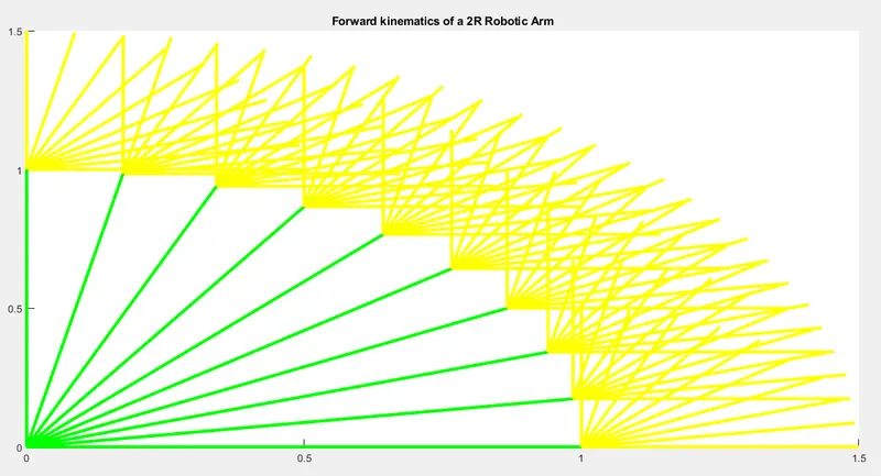
CONCLUSION: We got the plot.Each value of theta1,we change theta2 and link changing differently.Visualizing this plot is absurd.
Here we giving figure(ct) before plotting and ct= 1 which is outside of the for-loop.After the plot command ct=ct+1 is given.Each and every time for loop getting executed we incrementing it.We reduce the number of plots by decreasing theta1=4 and theta2=4.We get total 16 plots.
PROGRAM
% A program for different position of Arm for different values of angle
close all
clear all
clc

% Inputs

% Length of First link (L1),unit- meter
L1 = 1 ;

% Length of Second link (L2),unit- meter
L2 = 0.5 ;

% The inputs for the angle,unit- degree

theta1 = linspace(0,90,4) ;
theta2 = linspace(0,90,4) ;

% Angle changing using for loop
ct = 1 ;
 for i = 1 : length(theta1)
     THETA1 = theta1(i) ;
     for j = 1 : length(theta2)
         THETA2 = theta2(j) ;

         % Coordinate of L1 is (X0,Y0) at origin
         X0 = 0 ;
         Y0 = 0 ;

         % Coordinate of L1 is (X1,Y1) at the end
         X1 = L1*cosd(THETA1) ;
         Y1 = L1*sind(THETA1) ;


         % Coordinate of L2 is (X2,Y2) at the end
         X2 = X1+L2*cosd(THETA2) ;
         Y2 = Y1+L2*sind(THETA2) ;

         % Plotting
         figure(ct)
         line([X0,X1],[Y0,Y1],'linewidth',3,'color','g')
         line([X1,X2],[Y1,Y2],'linewidth',3,'color','y')
         title('Forward kinematics of a 2R Robotic Arm')
         ct = ct + 1 ;
     end
 end
PLOT
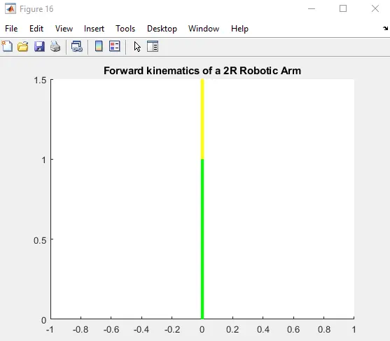
CONCLUSION: We got 16 plots total.Each plots basically repreasent a particular combinationof of theta1 and theta2.It repreasent how the robot ocuppied different position.This is not a very good way to repreasent plot.
To eradicate this convert line command into plot command.
PROGRAM
% The inputs for the angle,unit- degree

theta1 = linspace(0,90,4) ;
theta2 = linspace(0,90,4) ;

% Angle changing using for-loop
ct = 1 ;
for i = 1 : length(theta1)
    THETA1 = theta1(i) ;
    for j = 1 : length(theta2)
        THETA2 =theta2(j) ;

        % Coordinate of L1 is (X0,Y0) at origin
        X0 = 0 ;
        Y0 = 0 ;

        % Coordinate of L1 is (X1,Y1) at the end
        X1 = L1*cosd(THETA1) ;
        Y1 = L1*sind(THETA1) ;

        % Coordinate of L2 is (X2,Y2) at the end
        X2 = X1+L2*cosd(THETA2) ;
        Y2 = Y1+L2*sind(THETA2) ;

        % Plotting
        figure(ct)
        plot([X0,X1],[Y0,Y1],'linewidth',3,'color','g')
        plot([X1,X2],[Y1,Y2],'linewidth',3,'color','y')
        ct = ct + 1 ;
    end
end
PLOT
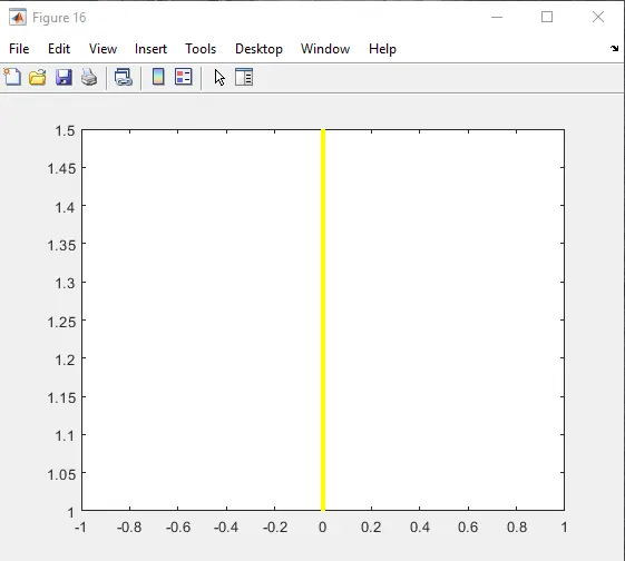
CONCLUSION: We got the 16 figure bur only one link is show here which is second link because when we give plot command most recent command is show here.To get rid of this we have to pass the command hold on.
PROGRAM
 % Plotting
        figure(ct)
        hold on
        plot([X0,X1],[Y0,Y1],'linewidth',3,'color','g')
        plot([X1,X2],[Y1,Y2],'linewidth',3,'color','y')
        ct = ct + 1 ;
PLOT
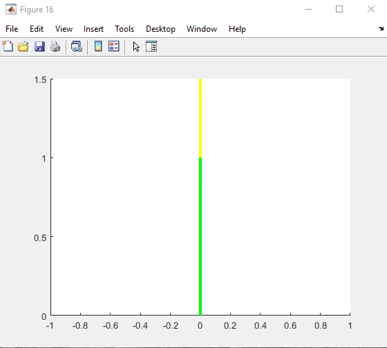
The advantage of using plot command is using pause command we get this below animation but it is not that good.
PROGRAM
% Plotting

        hold on
        plot([X0,X1],[Y0,Y1],'linewidth',3,'color','g')
        plot([X1,X2],[Y1,Y2],'linewidth',3,'color','y')
        pause(0.3)
        ct = ct + 1 ;
PLOT
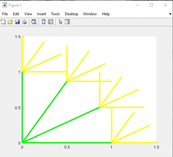
Here we remove the second plot command and modify the first plot as show below.Just have a single plot statement.
plot([X0,X1],[Y0,Y1],[X1,X2],[Y1,Y2],'linewidth',3)We execute the program and got the plot
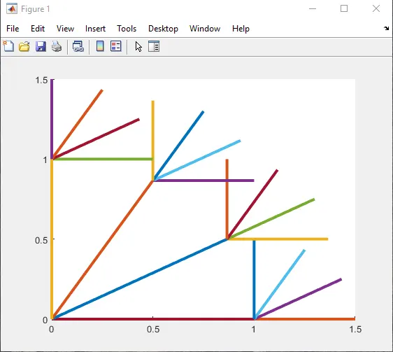
Here we get diiferent colors for each and every link.Then color changing randomly.
Now we remove the hold on command and fixing the axis.Then give the pause command to get the better result.
For x and y limit change we gave- ([-0.1 1.5 0 1.5]) and pause = 0.03.we can increase the value of theta1 and theta2 and we notice that for each value of theta1,theta2 is getting change.
To create Movie
Inputs given here, M(ct) =getframe(gcf) , ct represent here every figure window and getframe command represent here to getting the current figure. M is an array here where all the figures saved.
Then we create avi file
videofile = VideoWriter('forward_kinematics.avi') ;
open(videofile)
writeVideo(videofile,M)
close(videofile)
movie(M)
videofile = VideoWriter('forward_kinematics.avi','Uncompressed AVI') ;
open(videofile)
writeVideo(videofile,M)
close(videofile)
MATLAB PROGRAM
% A program for different position of Arm for different values of angle
clear all
close all
clc

% Inputs

% Length of First link (L1),unit- meter
L1 = 1 ;

% Length of Second link (L2),unit- meter
L2 = 0.5 ;

% The inputs for the angle,unit- degree
theta1 = linspace(0,90,10) ;
theta2 = linspace(0,90,10) ;

% Angle changing using for-loop
ct = 1 ;
for i = 1 : length(theta1)
    THETA1 = theta1(i) ;
    for j = 1 : length(theta2)
        THETA2 = theta2(j) ;

         % Coordinate of L1 is (X0,Y0) at origin
         X0 = 0 ;
         Y0 = 0 ;

         % Coordinate of L1 is (X1,Y1) at the end
         X1 = L1*cosd(THETA1) ;
         Y1 = L1*sind(THETA1) ;

         % Coordinate of L2 is (X2,Y2) at the end
         X2 = X1+L2*cosd(THETA2) ;
         Y2 = Y1+L2*sind(THETA2) ;

         % Plotting


         plot([X0,X1],[Y0,Y1],'g',[X1,X2],[Y1,Y2],'y','linewidth',3) ;
         axis([-0.1 1.5 0 1.5]) ;
         title('Forward kinematics of a 2R Robotic Arm Animation')
         pause(0.03) ;
         M(ct) = getframe(gcf);
         ct = ct + 1 ;
    end
end

movie(M)
videofile = VideoWriter('forward_kinematics.avi','Uncompressed AVI') ;
open(videofile)
writeVideo(videofile,M)
close(videofile)
OUTPUT
Here the animation video we create -