Week -2
QUESTION NO.:-1
Problem Statement :- Make a Simulink model of Doorbell using solenoid block with the following details:
when the switch is closed the electromagnet receives electrical power from the battery and pulls the metal arm to hit the bell producing sound.
Create a situation where the switch is closed for 2 seconds and then released. Observe the physical movement of the plunger.
Step 1 :- Identify problem statement and condition logic to be implemented
In above question, we observe that there is a solenoid when switch is closed the electromagnet receives electrical power from the battery and induced emf (electromagnetic force) push the plunger to hit the bell producing sound.when switch is opened the electric power from battery get cut and spring force pull the plunger toward its initial position.
Step 2 :- Create Simulink Model for given condition
List of the block required for creating Simulink Model-
- Solenoid- This block implements the electrical and mechanical characteristics of a solenoid.
- DC Voltage Source - The DC Voltage Source block maintains a constant voltage across its output terminals, independent of the current through the source.
- Electrical Reference - The Electrical Reference block represents an electrical ground.
- Switch - The Switch block models a switch controlled by an external physical signal. If the external physical signal PS is greater than the value specified in the Threshold parameter, then the switch is closed, otherwise the switch is open.
- Pulse Generator - The Pulse Generator block generates square wave pulses at regular intervals.
- Ideal Translational Motion Sensor - The Ideal Translational Motion Sensor block represents a device that converts an across variable measured between two mechanical translational nodes into a control signal proportional to velocity or position.
- Mechanical Translational Reference - The Mechanical Translational Reference block represents a reference point, or frame, for all mechanical translational ports. All translational ports that are rigidly clamped to the frame (ground) must be connected to a Mechanical Translational Reference block.
- Simulink-PS Converter - The Simulink-PS Converter block converts the input Simulink signal into a physical signal.
- PS-Simulink Converter - The PS-Simulink Converter block converts a physical signal into a Simulink output signal.
- Scope - This block is used to show result.
- Solver Configuration - Solver Configuration block specifies the solver parameter that need before beginning of simulation and this is mandatory for all simscape model.
The connection of above all the blocks is shown in the following image.
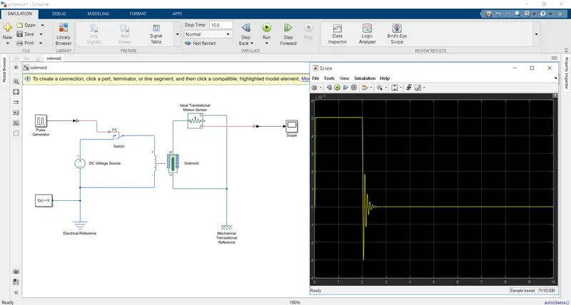
Explanation of Simulation Model - First I take solenoid block ,which shows 5 mm movement of its port R away from port c under excitation.Then I connected this solenoid block to a DC voltage source (50V) through a switch which PS port connected to a Pulse Generator which generate square wave pulse (pulse width 20% of period).Then I connect all electrical block to a Electrical Reference.After that I connect Port R of Solenoid to a Ideal Translational Motion Sensor which sense the position of port R and send signal to Scope.Then I connect Port C of Solenoid and Ideal Translational Motion Sensor to a Mechanical Translational Reference.
Result :- The result of given Simulation Model is shown in above image.When switch is closed for 2 sec that time plunger of solenoid shows 5 mm movement and hit the bell producing sound. After 2 sec , switch is opend then plunger return to its initial postion with the help of spring force.
NOTE :- Simulation model file "solenoid.slx" attached
****************************************************************************************************************************************************************************************************************************************************************************************************************************************************
QUESTION NO.:-2
Problem Statement :- Use a thermistor to sense the temperature of a heater & turn on or turn off the fan as per the below conditions:
Temperature source: 20 °C from 0 to 10 seconds, 27 °C from 10 to 30 seconds, 23 °C from 30 to 50 seconds
Fan conditions: ON if the temperature above 25 °C, OFF otherwise
Step 1 :- Identify problem statement and condition logic to be implemented
In above question, we observe that there is a thermistor which sense the temperature and based on this input it turn off or turn on fan.
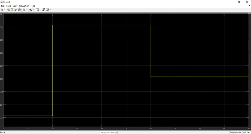
Input:- for 0 to 10 sec temperture is 20 deg cel (293.15K)
for 10 to 30 sec temperture is 27 deg cel (300.15K)
for 30 to 50 sec temperture is 23 deg cel (296.15K)
Output:- Fan ON if temperature > 25 deg cel (298.15K)
Fan OFF if temperature < 25 deg cel (298.15K)
Step 2 :- Create Simulink Model for given condition
List of the block required for creating Simulink Model-
- Thermistor :- Thermistor block is used to to sense temperature and based on that it shows resistance value.
- Voltage Sensor :- is a device that converts voltage measured between two points of an electrical circuit into a physical signal proportional to the voltage.
- Current Sensor :- is a device that converts current measured in any electrical branch into a physical signal proportional to the current.
- DC Voltage Source - The DC Voltage Source block maintains a constant voltage across its output terminals, independent of the current through the source.
- Electrical Reference - The Electrical Reference block represents an electrical ground.
- Controlled Temperature Source :- The Controlled Temperature Source block represents an ideal source of thermal energy.
- Thermal Referenace :- This block represents a reference point in a thermal network where the temperature is equal to absolute zero.
- Step :- The Step block provides a step between two definable levels at a specified time.
- Sum :- The Sum block performs addition or subtraction on its inputs.
- Product :- The product block perform Multiply and divide on its inputs.
- Switch :- The Switch block passes through the first input or the third input signal based on the value of the second input. The first and third inputs are data input. The second input is a control input. Specify the condition under which the block passes the first input by using the Criteria for passing first input and Threshold parameters.
- Simulink-PS Converter - The Simulink-PS Converter block converts the input Simulink signal into a physical signal.
- PS-Simulink Converter - The PS-Simulink Converter block converts a physical signal into a Simulink output signal.
- Scope - This block is used to show result.
- Solver Configuration - Solver Configuration block specifies the solver parameter that need before beginning of simulation and this is mandatory for all simscape model.
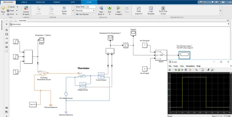
The connection of above all the blocks is shown in the following image
Explanation of Simulation Model :-
First I build Temperature Input siganal for given condition with the help of Step and Sum block then this output signal is given to the Port S of Controlled Temperature Source which Port A is connected to Theremal Reference and then this Temperature signal passed to Thermistor through Port B of Controlled Temperature Source.
Temperature input signal based on given condition is shown in below image.
After this , I give DC voltage supply to the Thermistor .For sensing voltage across Thermistor and current of circuit I used voltage sensor and current sensor respectively.This elecrical system is connected to a Electrical Reference.Output of voltage sensor and current sensor are given to Product block to calcualte Resitances values at vrrying temperature. In model we used NTC type Thermistor that shows decreased in resistance when temperature increased.
Following graph shows Resistance R at Temperature T
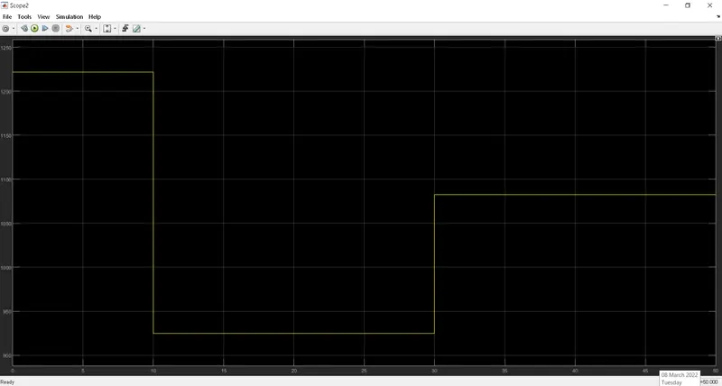
Above graph shows ,1000 ohm resistance at temperute 25 deg cel (298.15K).This is because of we take Referenace Termperature 298.15K and corresponding nominal Resistance 1000 ohm in Thermistor Electrical parameter setting.
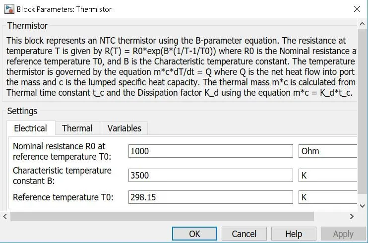
I used this referance resistance value (1000 ohm) in Switch Block for passing input signal.
Above Resistance signal value then given to Sum block where I convert this siganl into negative value .
This negative resistance signal given to input 2 of switch block where it compare with threshould value (-1000).
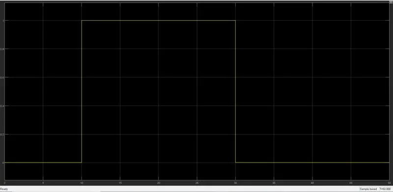
Result :- When input signal greater than threshould value of switch then switch gives output 1 (means Fan ON) otherwise output 0 (means Fan OFF).
The result is shown in following graph
NOTE :- Simulation model file "Thermistor.slx" attached