Week -2
1. Make a Simulink model of Doorbell using solenoid block
INROTDUCTION:
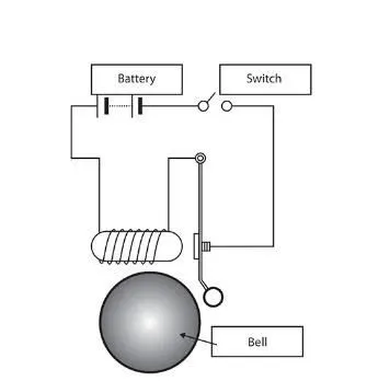
To make a simulation model of doorbell using solenoid block and create a situation where the switch is closed for two seconds and then released. observe the physical movement of the plunger. This simulation is use to show the movement of the plunger when the coil is disconnect.
MODELING:
In this model we create a simple doorbell like setup to solve the problem by using main block as solenoid block for simulate the desire output . When we apply a voltage to the coil its create a magnetic field which creates a force in the plunger it will create a mechincal movement. This movement is use to produce a sound in the bell but we only focus on how the plunger react when the disconnect the coil after two seconds.
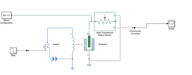
solenoid block
This block implements the electrical and mechanical characteristics of a solenoid. Parameterization is in terms of two points [X1,F1] and [X2,F2] on its force-stroke curve for a 100 percent duty cycle at Rated voltage Vdc and Rated current Idc where X2>X1>0 are stroke values and F1>F2>0 are corresponding forces. The plunger fully in (i.e. air gap closed) corresponds to X=0, and pull-in force is assumed to decrease quadratically with the magnitude of X. To ensure the force remains finite, the following condition should hold: X2/X1>sqrt(F1/F2). The plunger Maximum stroke is implemented as a hard stop, the dynamics of which are set by the Contact stiffness and Contact damping parameters. The same parameters are used to model the contact dynamics when the plunger pulls fully in. The Spring constant parameter is used to implement a spring force that pulls the plunger out, and can be set to zero.
Idea translation motion sensor
This block measures velocity or displacement in a mechanical translational network. The sensor is ideal since it does not account for inertia, friction, delays, energy consumption, and so on. The physical signal ports V and P report the velocity and position, respectively, of port R relative to port C. The measured velocity is positive when the velocity at port R is greater than the velocity at port C.
Switch
The block represents a switch controlled by an external physical signal. If the external physical signal PS is greater than the threshold, then the switch is closed, otherwise the switch is open. The closed resistance is defined by parameter R_closed, and the open conductance is defined by parameter G_open. Both parameters must be greater than zero.
Battery
It produce a desier voltage to the solenoid for the proper working just act as a power supply.
Step
Step is use to controll the switch. It works between the two state like starting stage its contain any value after some time (STEP TIME ) it will conver to another stage.
Converters
This block is use to convert the simulink to simscape vice versa.
Scope
This block is use to view the result in the plot and use to analyse the data.
Slover
This block is main block is use to slove the all equation in the background in above blocks.
RESULT
The simulation clearly show that, After two seconds the switch disconnects so no power go through the coil, so no magnetic field and the plunger goes to the orignal stage but it wil take time to settle.
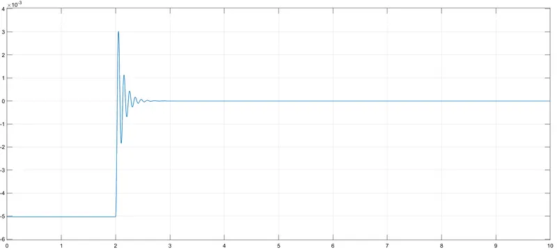
In statring stage at zero time the switch is ON so the plunger moves to 0 position to -5 position. after a two seconds the switch is off the plunger try to goes its orignal position but due to the inertia of the plunger it create force on the spring is decompressed so the oscillation is created. It take times to go steady state, In this above graph shows that plunger takes one second to get a steady state.
CONCLUSIONS
We properly simulate the model and Observe the physical movement of the plunger.
2.USE A THERMISTOR TO SENSE THE TEMPERATUE OF THE HEATER AND TURN ON OR OFF THE FAN
INTRODUCTION
Use a thermistor to sense the temperature of a heater & turn on or turn off the fan as per the conditionsemperature source: 20 °C from 0 to 10 seconds, 27 °C from 10 to 30 seconds, 23 °C from 30 to 50 seconds.
Fan conditions: ON if the temperature above 25 °C, OFF otherwise
MODELING
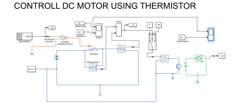
First create the signal for input for controll thermal source block, so we use signal builder block and create our signal for the problem. Then apply power to the thermistor and measure the voltage drop and current flow through the circuit by using the voltage sensor and current sensor. Then use this values as a input to divide block to find the resistance value. Use the value to create a switch condition for controll the controlled voltage block to operate the DC motor and measure the angular velocity of the DC motor by use the ideal rotational sensor. Scope is use to plot all the value in graph.
Use simulink to model and simulate, then use to solve the problem In this model various type of blocks are use.
- Thermistor
- Heat soure
- Dc motor
- Sensors
- Scops
- Other peripherals
THERMISTOR
Thermistor is act like resistor but its resistance value change in different temperature. When the temperatur is increase the resistance value is decrease and temperature value is decrease the resistane value is increase like vice versa we measure the voltage drop between the resistor and use to controll any modules. It required a heat source to create a temperatur different for the simulation
SOURCES
We use two different type of sources for the total simulation are
- HEAT SOURCE
In this simulation we use controll heat source for varing temperture values. So we use signal builder to produce different signal as per the given problem the signal builder graph show below.
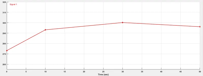
We convert values from celcies to kelvin for all blocks and use thermal referance block to get referance.
- ELECRICAL SOURCE
Battery is use to supply the power to the thermistor and the controll power source is use to produce the power to the dc motor as consider as a fan. The controll power source is controll by the switch.
DC MOTOR
DC motor is use as a fan to get output. Use the controll power supply as a input and motion sensor to the angular velocity. and all parameter set as a assumption. So it just output for the simulation.
SENSORS
we use different types of sensor to get the output are
- Voltage sensor
- Current sensor
- Ideal rotational motion sensor
VOLTAGE SENSOR
This sensor are use to get the voltage value, drops across the thermistor and is use to further calculation.
CURRENT SENSOR
This sensor block use to know, how much current is flow through the thermistor and it also use for calculation.
IDEAL ROTATIONAL MOTION SENSOR
This sensor is use to know the angular velocity and angle of shaft in the DC motor. This sensor also required a mechnical rotation referance block as a referance point.
SCOPE
Scope is use to plot the values form the sensor. It also use to study the graph helps to slove the problem.
OTHER PERIPHERALS
DIVIDE
Devide block is use to divide a given input. In this problem we use this block to get the resistance value by dividing the voltage by current (R=V/I) for know how temperatue affect the resistance.
SWITCH
Switch block is use to switch between two values. when the condition is true output is switch to another value.
SOLVER
Solver is use to slove all simscape background equation.
CONVERTERS
Coverters use to link the simulink to simscape and vice versa. We enable the filters for coverters used between in signal builder and controll thermal source.
RESULT
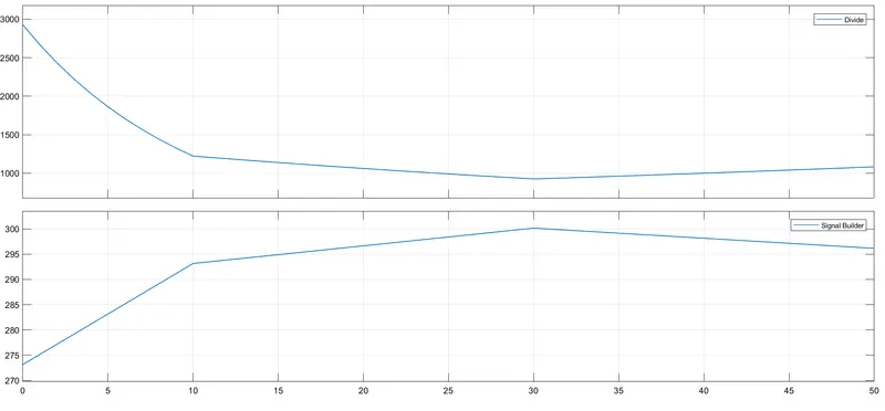
The above graph shows. When the temperture increase it will decrease the resistance.
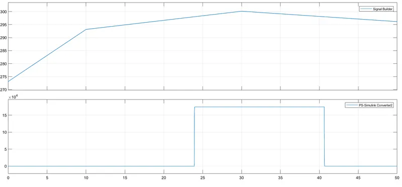
This graph show temperatur rise above 25 degree celcies. The motor will ON and temperature goes below 25 degree celsies motor will OFF.
CONCLUSTION
This model work properly as per the given problem.