To create a Simulink model of Doorbell using solenoid block and to create a Simulink model using thermistor to sense the temperature of a heater and Turn ON or Turn Off the fan.
Simulink for Mechanical & Electrical Engineers
To create a Simulink model of Doorbell using solenoid block and to create a Simulink model using thermistor to sense the temperature of a heater and Turn ON or Turn Off the fan.
1. To make a Simulink model of Doorbell using solenoid block.
Objective:
- To make a Simulink model of Doorbell using solenoid block such that the switch is closed for 2 seconds and then released. Also the physical movement of the plunger should be observed.
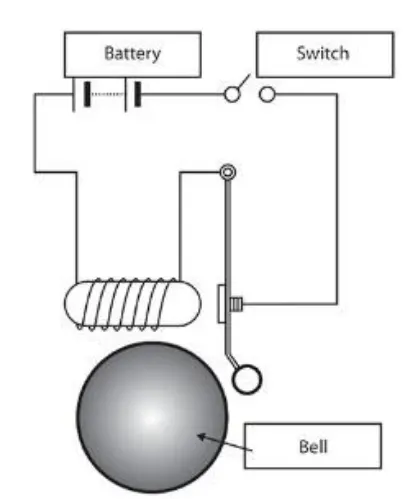
Description:
The doorbell mainly works on the principle of electromagnetism. Electromagnets are coils of wire wrapped around a small piece of a magnet metal. When electricity passes through the wire, it creates a magnetic field around the wire. When switch is ON, the circuit becomes active and the solenoid activates the plunger that creates the doorbell sound. The basic componets in the doorbell are a Battery, Switch, Solenoid, and a Bell with plunger.
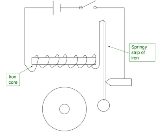
A doorbell uses a electromagnet which is called a solenoid. A solenoid is a electromagnet where the coiled wire surrounds a metal piece/block. A solenoid converts electrical energy into mechanical work. Here the coil is made of turns by the copper wire. When the current flows through wire, strong magnetic flux is generated. This solenoid activates and controlls the the plunger that is attached to it and hence the bell rings.
Simulink Model:-
Explanation:-
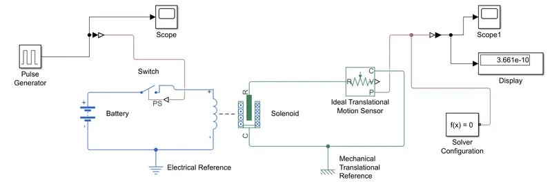
- The above model shows the complete circuit of a door bell. Main parts in the doorbell are switch, solenoid, battery, bell and a plunger.
- Initially, the solenoid block is consideredin which it represents a actual solenoid. Along with this battery block is also used from the simscape library.
- The solenoid and battery are connected with the terminals.
- In order to control the current flow between the battery block and the solenoid block, a Switch Block is placed. The switch block models as switch controlled by an external physical signal. If the physical signal PS is greater than the value specified in the threshold parameter, then the switch is closed, otherwise the switch is open.
- Now, the battery block, switch block and the solenoid terminals are grounded with Electrical Reference.
- Electrical Reference block is also called as the electrical ground. In the above system, this is connected towards the negative terminal of the battery and the solenoid.
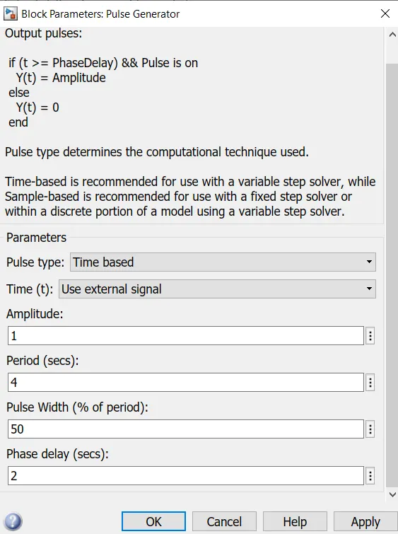
- As the switch is controlled by the physical signal, the PS port in the switch block is connected with the pulse generator. By changing the parameters we can controll the switch block. In this case the following settins wer made in order to get the required criteria;
Setting of Pulse Generator:
- As per the settings in Pulse Generator- it is specified that Amplitude=1, Period(sec)=4, pulse width(% of period)=50, phase delay(sec)=2. Initially the pulse is at zero.
- As the phase delay is set to 2sec, untill 2sec the pulse will be zero. After the 2sec the pulse will raise from 0 to 1 (as amplitude is set to 1) which means for next 2sec the pulse will be at amplitude-1.
- And at 4th second, it will come back to zero. For the next 2sec it will at zero. And hence The cycle completes the period of 4sec.In this way the cycle continues.
- Now, consider the solenoid block i.e. we have two ports 'R' & 'C'. Where R represents the plunger operation and C is the constant point.
- The port-R in solenoid is connected to the port-R in the Ideal Translation Motion Sensor Block. This continously senses the position of the plunger and gives the output.
- In the Ideal Translation Motion Sensor there are 3 different connections in the output side i.e connections 'C', 'V', 'P'.Where 'V' & 'P' are the physical signal output ports for the velocity and the position.
- In this simulation, only the position of plunger is studied and recorded. Connection 'V' is left blank.
- The port-C of solenoid is connected to the connection-C of the output of Ideal Translational Motion Sensor Block. Also both these connections are connected to the Mechanical Translation Reference.
- AS connection-'P' indicates the position of plunger, it is connected to a PS-Simulink Converter. This converter, converts the input physical signal to a simulink output signal.
- This PS-Simulink Converter is then connected to a Scope Block which generates a plot/graph showing the position of plunger from port-P of Ideal Translation Motion Sensor.
- Solver configuratiom block is connected to the model. Each physical network represented by a connected simscape block diagram require solver settings information for simulation.
- Finally the simulation is set to Run by setting the stop time for 10sec.
Results:
- After successfully running the simulation, the result can be visualized by using scope and also display block which shows the output value.
- From the simulink model, the Scope that is connected to the Pulse Generator displays the Amplitude vs Time plot i.e. it displays the pulse behaviour.
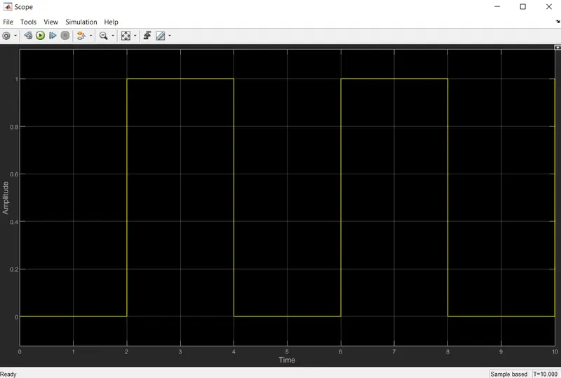
- Based on the input data that is given in Pulse Generator Block, the above plot shows the pulse generation.
- This plot shows the situation where the switch is closed for 2 seconds and then released.
- As per the declared values, pulse generation has started after 2 seconds.
- At 2 seconds the amplitude maintained is 1 and then again for next 2 seconds the pulse is maintained zero.
- From the plot it is clear that, when amplitude is maintained at value 1 then the switch will be Turned Off and when it is zero the switch will Turn On.
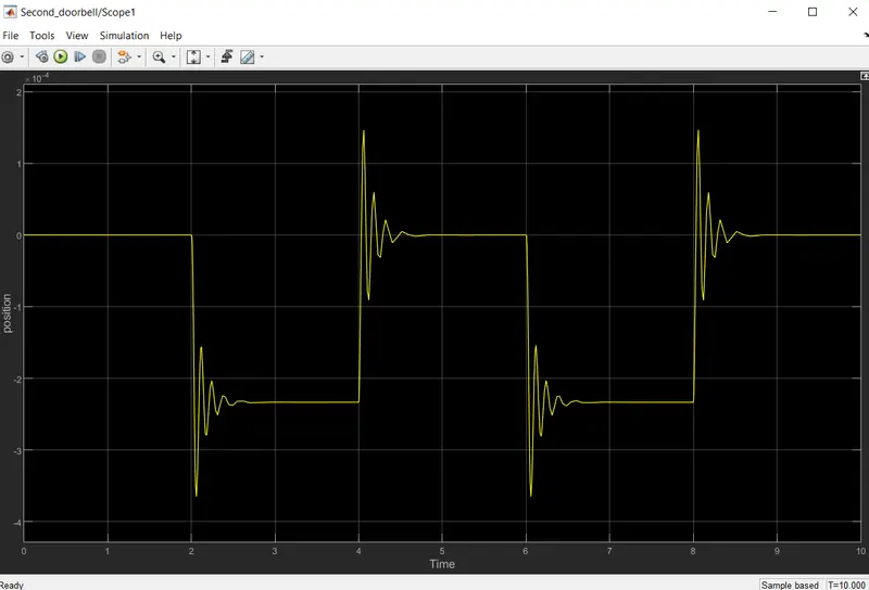
- From the simulink model, the 'Scope1' that is connected to the Ideal Translation Motion Sensor block displays the Position of plunger vs Time plot.
- The above plot shows the position of plunger at various time intervals.
- When we compare the Pulse Generator plot with the Position vs Time plot, it is observed that for the given time intervals the bell rings i.e. the bell start ringing at the interval of 2sec with the given phase delay of 2sec.
Conclusion:
A Simulink model of Doorbell using solenoid block is built. Using this model a pysical bell phenomina is developed where the switch is closed for 2 seconds and then released. Also the physical movement of the plunger is observed from the output plot.
2. To make a Simulink model using thermistor to sense the temperature of a heater and turn on or turn off the fan.
Objective:
- To make a Simulink model using a thermistor to sense the temperature of a heater and Turn On or Turn Off the Fan.
Conditions:
Temperature source to be maintained is 20 °C from 0 to 10 seconds, 27 °C from 10 to 30 seconds, 23 °C from 30 to 50 seconds. And the Fan conditions is kept ON if the temperature is above 25 °C, otherwise OFF.
Description:
A thermistor is defined as a type of resistor whose electrical resistance varies with changes in temperature. Generally, the resistance of thermistor is measured using an ohmmeter. Mainly there are two types of thermistors, they are Positive Temperature Coefficient Thermistor(PTC) and Negative Temperature Coefficient Thermistor(NTC). The PTC thermistors are the resistors with a positive temperature coefficient i.e. the resistance increases with increasing temperature. Whereas, the NTC thermistors are the negative temperature coefficient i.e. the resistance decreases with increasing the temperature. The type of material used in the thermistor will dictate how much the resistance changes, which is changed with temperature.
Simulink Model:-
Explanation:-
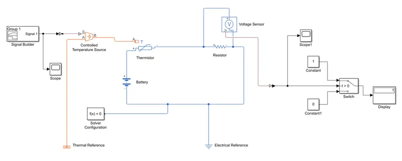
- In order to create a Cooling Fan Model using Thermistor, we need a signal builder, controlled temperature source, thermal reference,thermisor, battery, resistor, voltage sensor, logical switch, electrical reference, constants, switch and scope blocks.
- In the above model the input signal is fed using a Signal Builder block. The data her is set using the initial conditions i.e. Temperature source to be maintained is
20 °C from 0 to 10 seconds,
27 °C from 10 to 30 seconds,
23 °C from 30 to 50 seconds.
Fan is kept ON if the temperature is above 25 °C, otherwise OFF.
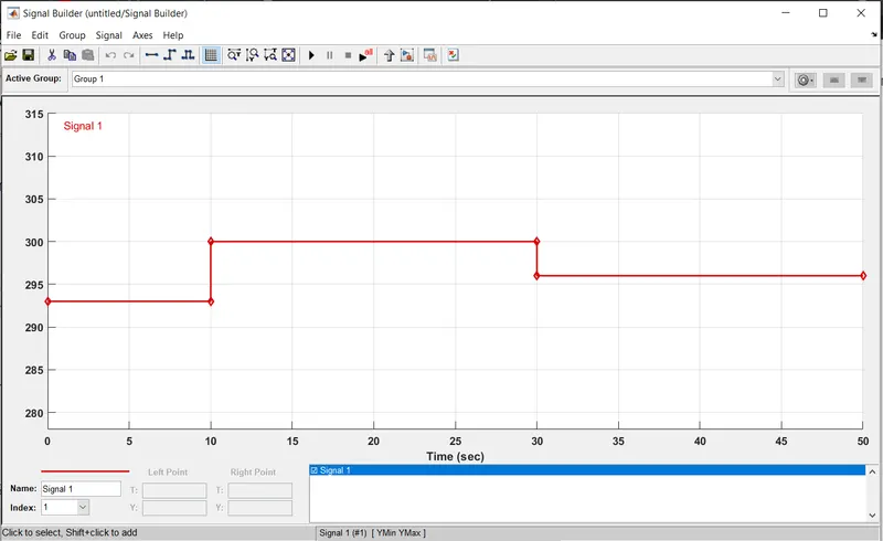
- Further, this signal is fed into the controlled Temperature Source Block by means of a Simulink PS converter. Scope block is connected to the Signal Builder to check the input signal.
- The port-S of Controlled Temperature Source block is is connected with Simulink PS converter, and the port-A is connected to the thermal resistance .
- The signal from signal builder is fed into port-A of the thermister. The positive side of thermistor is connected to the +ve terminal of the battery and the -ve side of thermistor is connected to the Voltage Sensor block.
- In the thermistor block, in the Variable window the priority level is set to LOW.
- In between the terminals of the voltage sensor block the resistance block is placed and it is is set to 1 ohm.
- The negative terminal of the battery and the negative terminal of the voltage sensor are grounded with Electrical Reference.
- The port-V from the sensor is connected to the Scope block by using PS-Simulink Block. This converts the input physical signal to a simulink output signal. The value obtained is displayed in the Display Block.
- The PS- Simulink converter is used to connect the Switch(connected to centre terminal), for the other two terminals of switch constants block is connected.
- To give the threshold value in the Switch Block, it has 2 conditions i.e. if the value is above the threshold value of the output will be 1 and if the value is below the threshold value of the output will be 0.
- Inorder to set the threshold value of Switch, double click on the switch block and edit the the value of threshold as obtained to get the required cutoff value.
- Also one more connection from the PS-simulink converter to Switch block is extended and connected to the Display Block.
- After setting the threshold value for the switch, we need to run the simulation for stop time of 50sec and the plot is observed in the Scope2.
- The final output is recorded in the scope and the value is moniterd in the Display block.
Results:
- After successfully running the simulation, the result can be visualized by using scope and also display block which shows the output value.
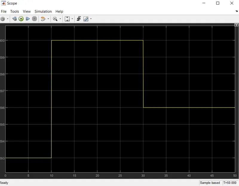
- The trend of the input parameter signal[Scope] is visualized and then its compared with the output signal[Scope1].
Scope:[Input parameter from Signal Builder]
Temperature source to be maintained is 20 °C from 0 to 10 seconds, 27 °C from 10 to 30 seconds, 23 °C from 30 to 50 seconds.
Scope1:[Signal generated at output w.r.to the given temperatures]
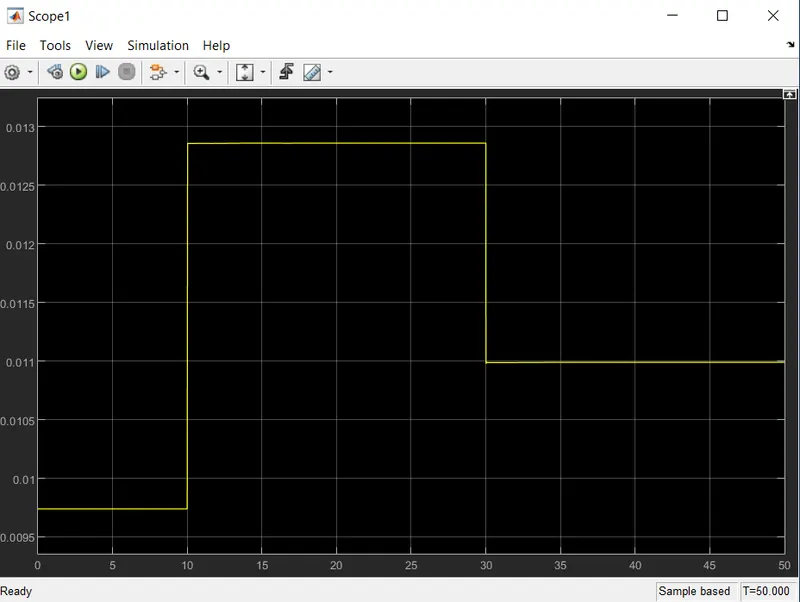
- From the above plot, the changes in voltage with the change in temperature is observed. By using this signal we can set the condition for ON & OFF.
- It shows that in the range of 0-10sec it has a temperature of 293k in which the voltage is optained between 0.0095 & 0.01. For the range of 10-30sec it has temperature of 300k in which the voltage is obtained close to 0.013, and for the range of 30-50sec it has temperature of 296k in which the voltage is obtained is around 0.011.
- Required criteria is the fan should be ON when the temperature is more than 25deg Celsius. Hence from the above graph when the voltage is more than 0.011 (296K) the Fan should be ON & when the voltage is below the threshold value the fan shoud be OFF.
Scope2:[Fan ON & OFF phenomina by setting the threshold value]
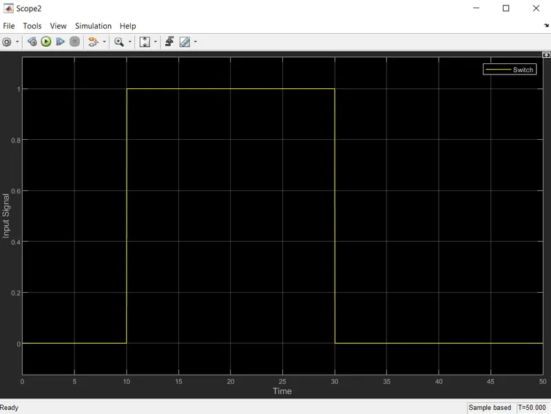
- Clearly, the above plot shows that at temperature greater than 296K i.e. in the time period of 10-30sec the Fan is turned ONN and in all other time periods it is turned OFF.
- Hence the Fan is ON if the temperature is above 25 °C, otherwise its OFF.
Conclusion:
- A Simulink model of Doorbell using solenoid block is created such that the switch is closed for 2 seconds and then released. Also the physical movement of the plunger is observed.
- A Simulink model using a thermistor to sense the temperature of a heater is created and parameters are set to Turn On or Turn Off the Fan based on the specified temperature and time.