Week 14 challenge
OBJECTIVE:
The objective of this project is to design a butterfly valve and apply GD&T to it's components and final assembly using Siemens NX.
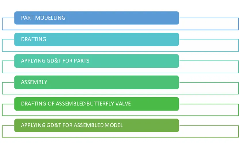
PROCESS PLAN:
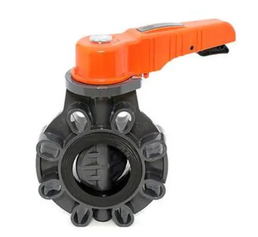
Description of Butterfly valve:
A butterfly valve is a valve that isolates or regulates the flow of a fluid. The closing mechanism is the disk that rotates. A butterfly valve is from a family of valves called quarter-turn valves.
In operation, the valve is fully open or closed when the disc is rotated a quarter turn. The "butterfly" is a metal disc mounted on a shaft. When the valve is closed, the disc is turned so that it completely blocks off the passageway.When the valve is fully open, the disc is rotated a quarter turn so that it allows an almost unrestricted passage of the fluid.
The valve may also be opened incrementally to throttle flow.There are different kinds of butterfly valves, each adapted for different pressures and different usage
The important terms of geometric dimensioning and tolerancing (GD&T):
- Feature control frame
- Datums and datum references
- Symbols
- Feature control frame:
A feature control frame is used in GD&T to describe the conditions and tolerances of a geometric control on a part’s feature. The feature control frame consists of four main pieces of information:
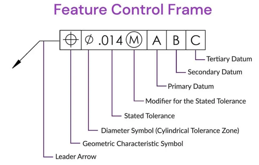
- GD&T symbol or control symbol
- Tolerance zone shape and dimensions
- Tolerance zone modifiers: material condition modifiers, projections…
- Datums and Datum references:
A datum is a virtual ideal plane, line, point, or axis. A datum feature is a physical feature of a part identified by a datum feature symbol and corresponding datum feature triangle. These are then referred to by one or more ‘datum reference’ which indicate measurements that should be made with respect to the corresponding datum feature.
An engineering datum used in geometric dimensioning and tolerancing is a feature on an object used to create a reference system for measurement. In engineering and drafting, a datum is a reference point, surface, or axis on an object against which measurements are made.
These are then referred to by one or more 'datum references' which indicate measurements that should be made with respect to the corresponding datum feature.
In geometric dimensioning and tolerancing, datum reference frames are typically 3D. Datum reference frames are used as part of the feature control frame to show where the measurement is taken from. A typical datum reference frame is made up of three planes. For example, the three planes could be one "face side" and two "datum edges". These three planes are marked A, B and C, where A is the face side, B is the first datum edge, and C is the second datum edge. In this case, the datum reference frame is A/B/C. A/B/C is shown at the end of feature control frame to show from where the measurement is taken.
- Symbols:
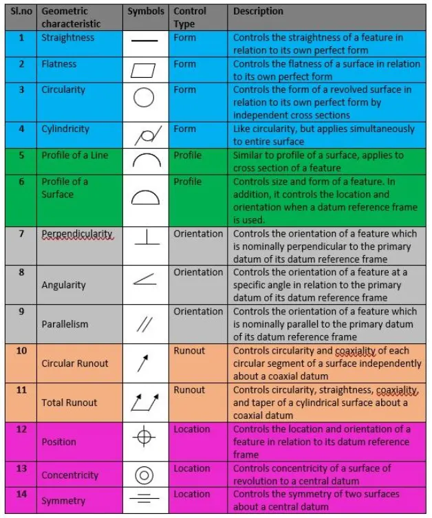
There are certain symbols used in geometric dimensioning and tolerancing to specify the geometric characteristic of the features. These symbols are present in the feature control frame to convey the actual position, size and modifiers of a particular features with respect to their datums.
- Advantages of applying GD&T:
- 1.Saving Money - GD&T enhances design accuracy by allowing for appropriate tolerances that maximize production.
- 2.For many projects, the process provides extra or bonus tolerances, further increasing cost effectiveness.
- 3.Offering Uniformity and Convenience - As a single, consistent language, GD&T reduces guesswork and interpretation while ensuring consistent geometries
- 4.Ensuring Dimensional and Tolerance Requirements — By explicitly stating all design requirements, a thorough GD&T process guarantees accurate fulfillment of all dimensional and tolerance specifications.
- 5.Providing Accurate Communication — Today’s intricate designs demand the most accurate and reliable communication. GD&T enables designers, manufacturers, and inspectors to communicate clearly with one other, saving time and making the process more efficient.
COMPONENTS OF BUTTERFLY VALVE:
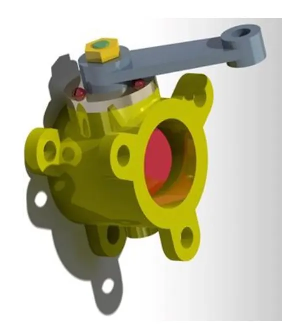
Various components of butterfly valve and GD&T applied to them are shown below.
1. BODY - BUTTERFLY VALVE
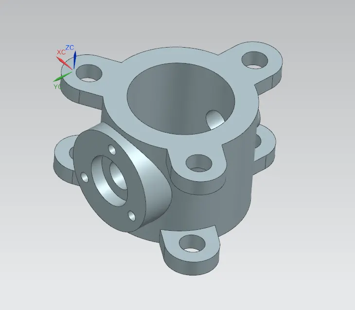
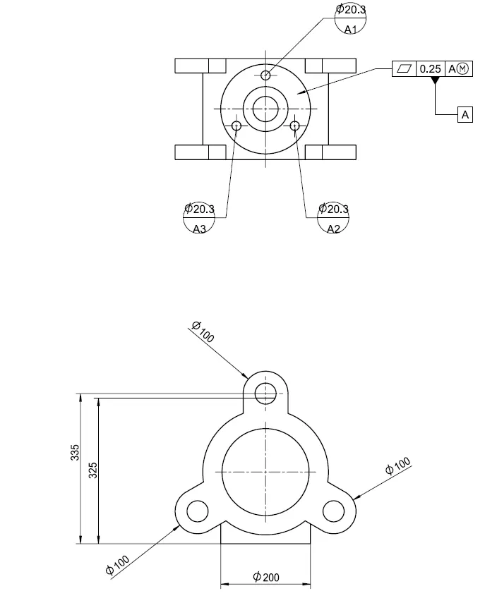
Butterfly valves are usually fixed between two pipleines using flange couplings. Body of our Butterfly valve and GD&T applied to the same using Siemens NX CAD are shown below.
2. SHAFT - BUTTERFLY VALVE
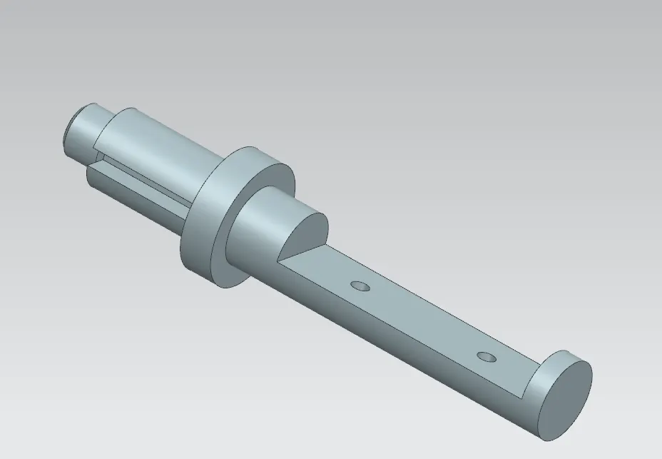
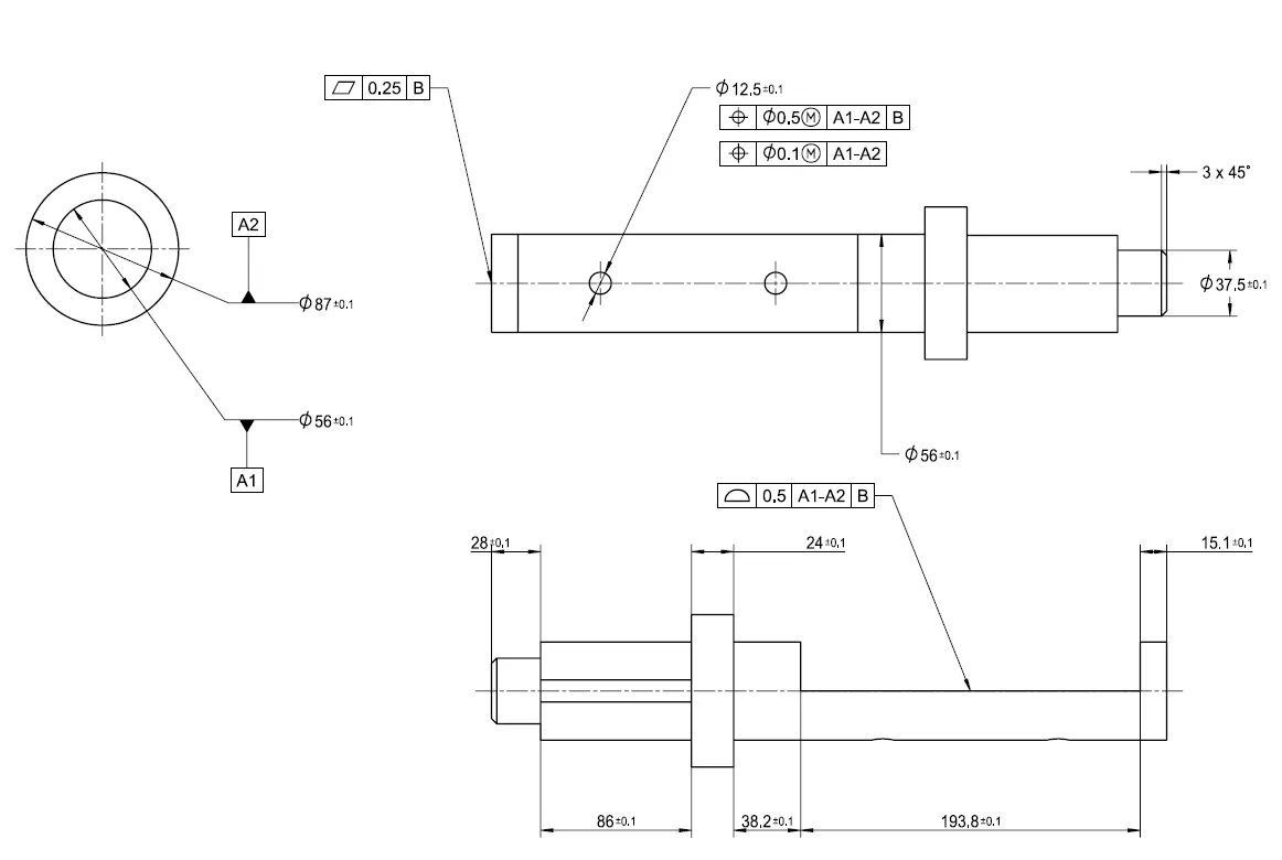
The disc/plate, lever and nut are assembled to this shaft.
3. DISC - BUTTERFLY VALVE
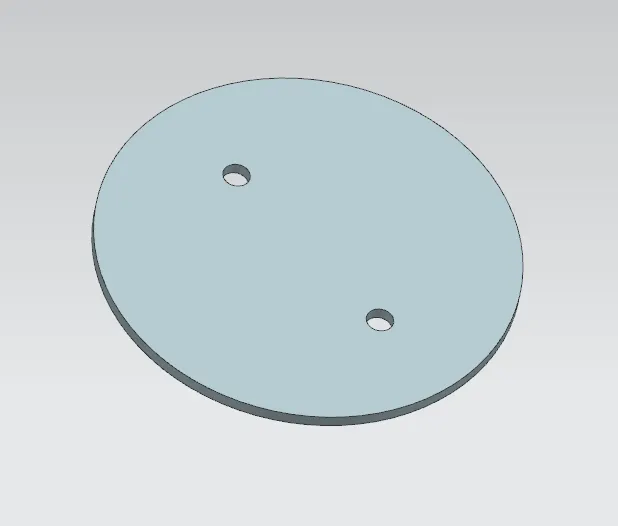
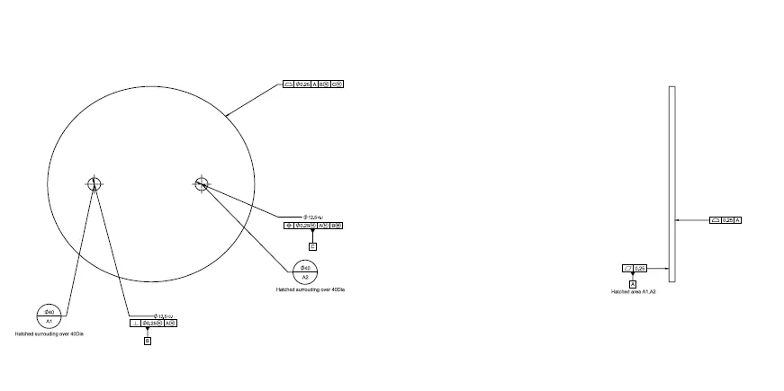
When valve is fully opened or closed the disc is rotated a quarter turn.Disc is mounted on shaft. When the valve is closed, the disc is turned so that it completely blocks off the passageway.When the valve is fully open, the disc is rotated a quarter turn so that it allows an almost unrestricted passage of the fluid.
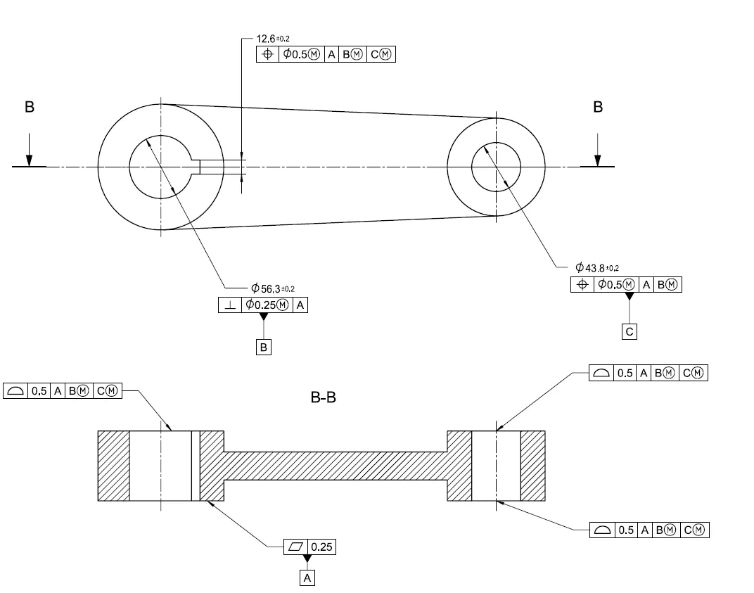
4. LEVER - BUTTERFLY VALVE
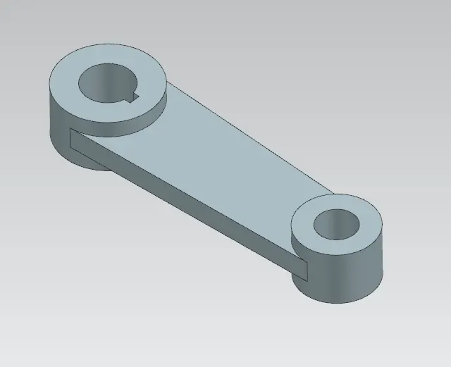
Lever is mounted at an end of shaft outside the body. Hand lever is usually used in small sized Butterfly valves. It is used to open or close the valve.
5. RETAINER - BUTTERFLY VALVE
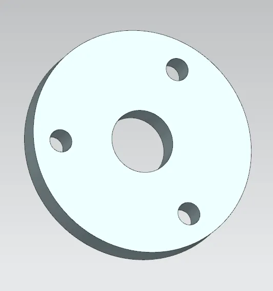
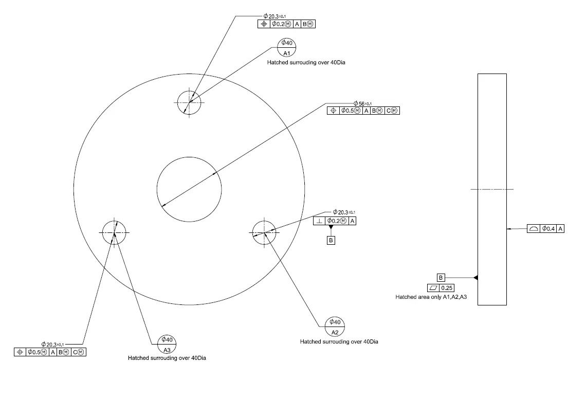
Retainer is a kind of washer fixed on the body of butterfly valve.
6. NUT - BUTTERFLY VALVE
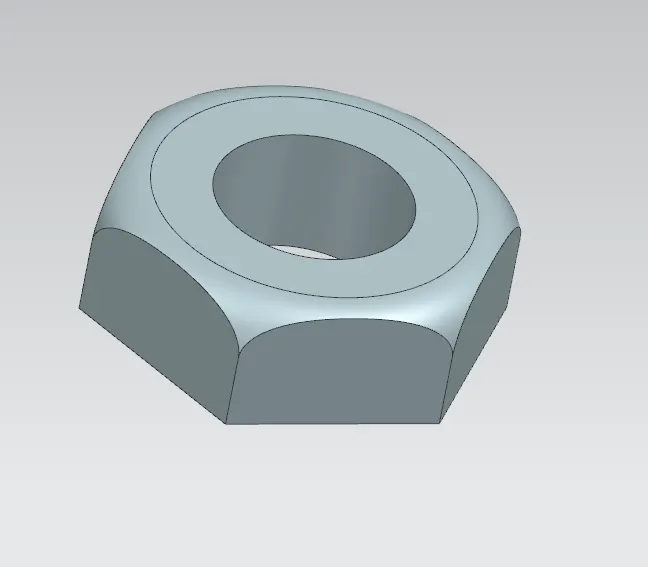
It is fixed at the top end of shaft to keep the lever and retainer on position relative to the body of butterfly valve.
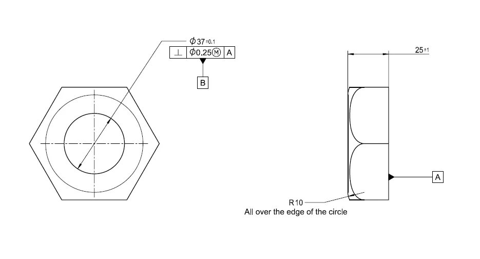
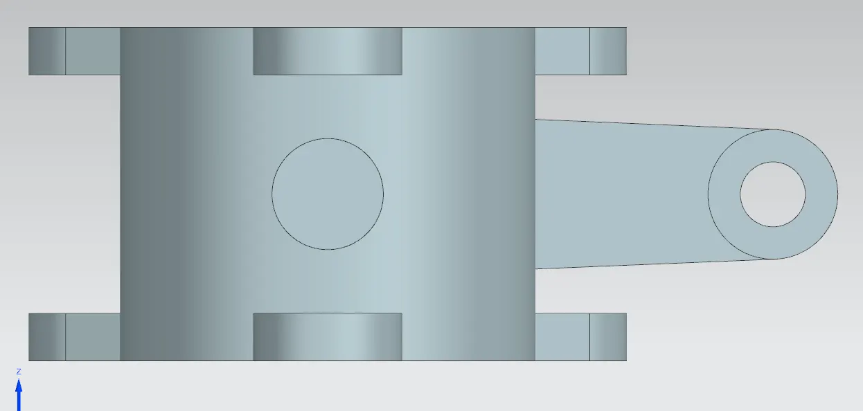
All Views of the Butterfly model:
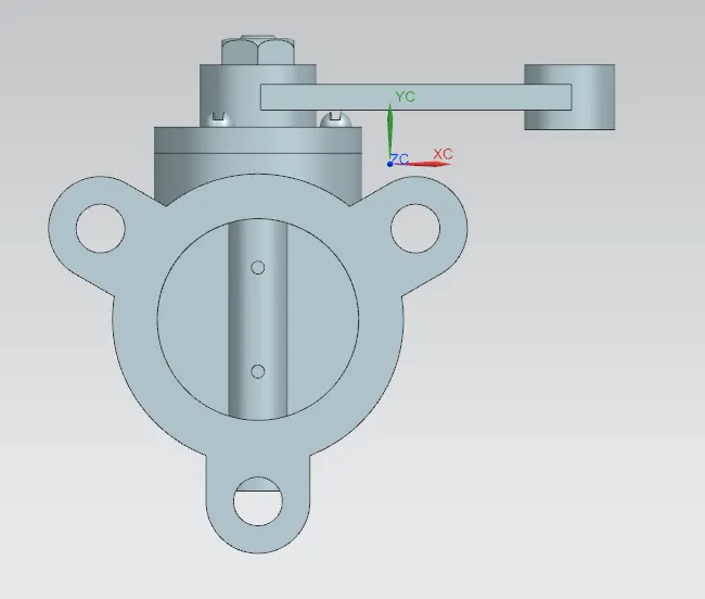
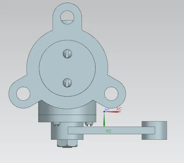
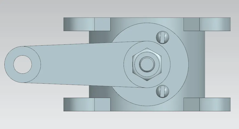
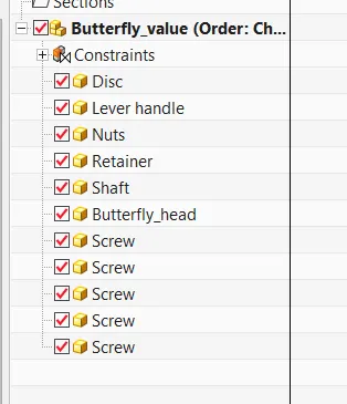
Assembly tree structure:
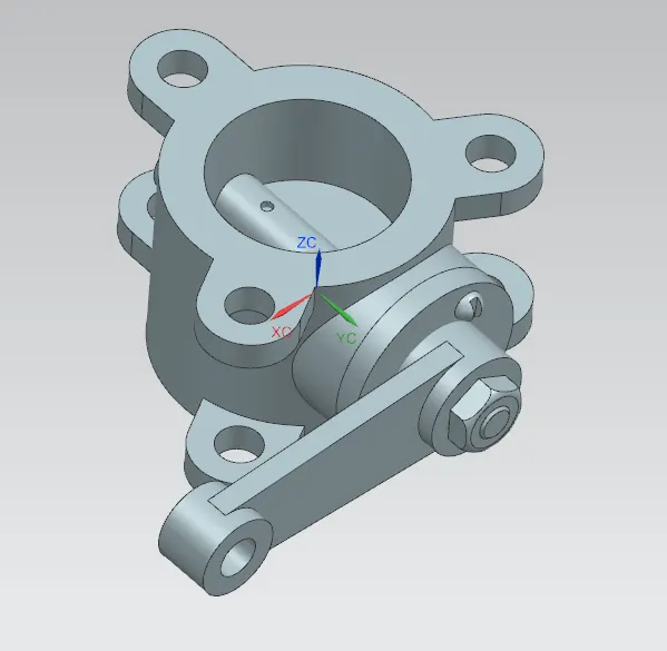
ASSEMBLY - BUTTERFLY VALVE:
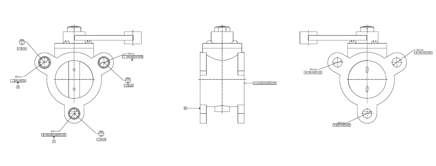
After completing the modelling of various components of butterfly valve, all parts were assembled together using Siemens NX Assembly workbench.
CONCLUSION
Butterfly valve was successfully designed and GD&T applied to all parts and the assembly of the Butterfly valve.