Week 14 challenge
AIM
Assemble all the components in assembly workbench of butterfly valve
Implement the GD&T fundamental and Denote it on Drawing Sheet for the assembly
INTRODUCTION
A butterfly valve belongs to a family of QUARTER-TURN valves. A butterfly valve is a flow control device that incorporates a rotational disk to control the flowing media in a process. The disk is always in the passageway, but being relatively thin, it offers little resistance to flow.
In operation, the valve is fully opened or closed when the disc is rotated a quarter turn. When the valve is closed, the disc is turned so that it completely blocks the passageway. And, when the valve is open the disc is rotated a quarter turn/90 deg so that it allows the unrestricted flow of the fluid. The valve may also be opened incrementally to throttle flow. Many different types of valves are used in flow control. They are used for a variety of reasons, such as phase (liquid or gases), pressure, piping restrictions, and solids content. Other valves are chosen for their capability to open and close in a quarter turn.
Early use of butterfly valves focused on water applications, but new designs and component materials have allowed them to be utilized in growing industrial fluid applications. Presently, butterfly valves can be found in almost every chemical plant handling a variety of diverse fluids.
COMPONENTS
BODY
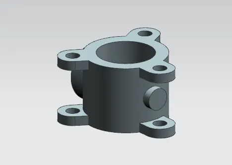
SHAFT-STEM
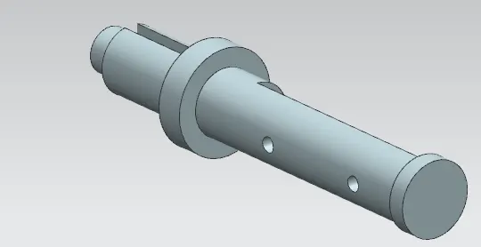
RETAINER
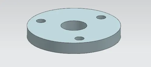
DISC
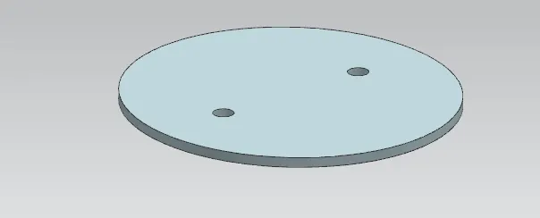
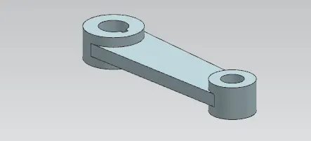
LEVER
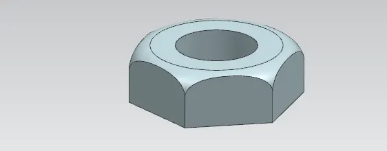
NUT
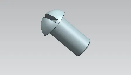
SCREW-RETAINER
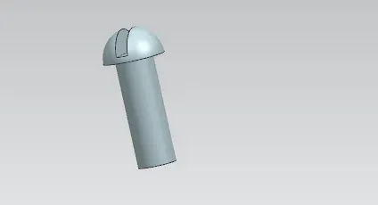
SCREW-DISC
ASSEMBLY
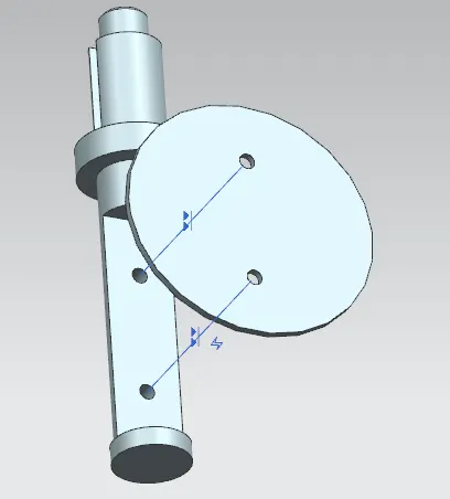
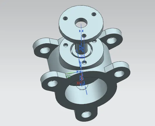
- Align the center axis of holes in disc and shaft
- provide touch constrain to face of shaft and bottomface of disc
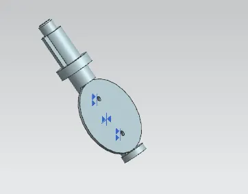
- Align the center axis of screw and center axis of disc
- provide touch constrain to inside face of screw and inside face of disc
- disc is assembled with shaft
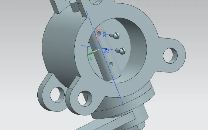
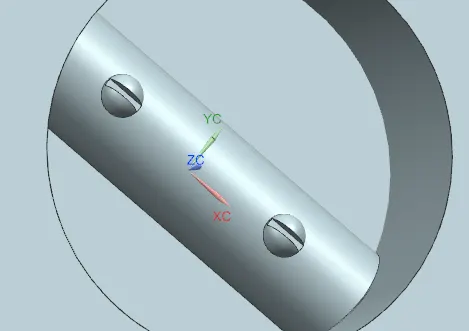
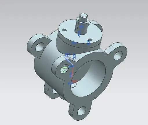
- Align the center axis of shaft and center axis of body
- provide touch constrain to inside face of body and side face of disc
- shaft is assembled inside body
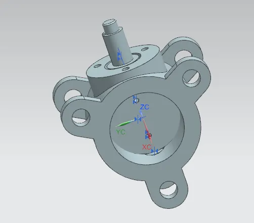
- Align the center axis of holes in retainer and body
- provide touch constrain to bottom face of retainer and body
- Align the center axis of screw and center axis of hole in retainer
- provide touch constrain to inside face of screw and face of retainer
- retainer is assembled in body
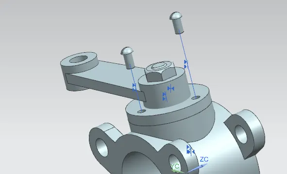
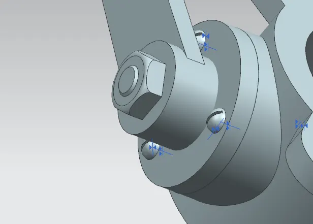
- Align the center axis of hole in lever and shaft
- Align the edge of slot in lever and slot in shaft
- handle is assembled
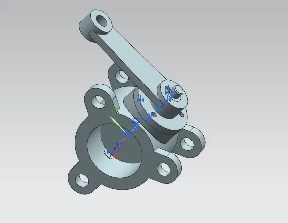
- Align the center axis of nut and shaft
- provide touch constrain to bottom face ofnut and retainer
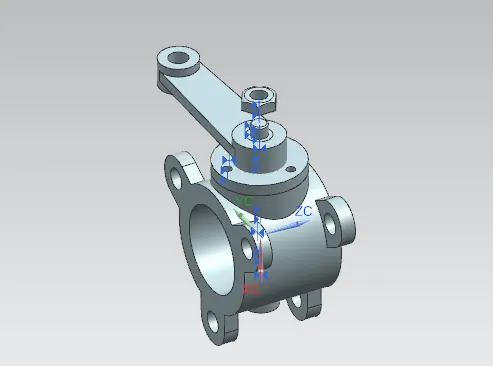
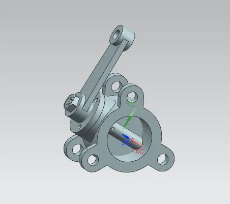
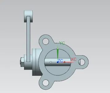
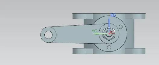
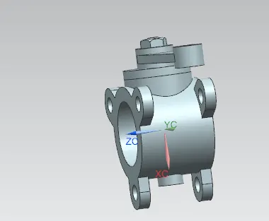
BUTTERFLY VAVLE ASSEMBLY IS CREATED
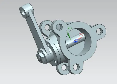
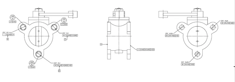
DRAWING SHEET WITH GD&T
- Instead of putting complete surface, datum target area A1,A2,A3 is provided with flatness of 0.25 to form datum A
- the part make contact with three holes
- One hole become datum B and provided with a perpendicularity of 0.25 at MMC with respect to datum A
- Other become datum C and provided with position tolerance of 0.25 at MMC with respect to datum A and datum B at MMB.
- Third hole is provided with position tolerance of 0.5mm at MMC with respect to datum A and datum B and C at MMB to form datum D.
- the opposite surface is controlled with a profile of 0.5mm with respect to datum A and datum B and C at MMB
- The three holes in opposite surface needs to be coaxial with respective counterpart.
- so they are provided with a position tolerance of 0.75 at MMC with respect to counterpart Datum
CONCLUSION
- Assembled all the Parts of Butterfly Valve assembly in assembly work bench
- Applied GD&T symbol to the drawing sheet