Week 14 challenge
Aim:
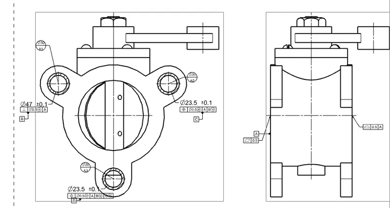
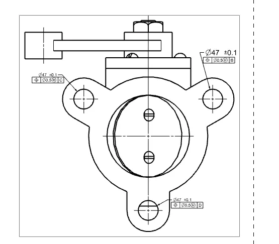
Assemble and apply Geometric Dimensioning and Tolerancing (GD&T or GD and T) to the betterfly valve assembly drawing
GD&T A Manufacturing Essential:
When engineers make up a design, they do much more than show lines, holes, curves, and even solids. Geometric dimensioning and tolerancing give the allowable amount of variation in a model, which every developer or manufacturer needs to know before they set up machines and start production. Nowadays, all manufacturing industries rely on the system of geometric tolerancing. Geometric dimensioning and tolerancing rules are applied to more part features than ever. The primary function of geometric dimensioning and tolerancing is to accomplish
international standards to save time and money.
A process that used to take long hours ten years ago, and in most cases considered impractical, is now able to verify finished parts to meet the design requirements in minutes due to geometric dimensioning and tolerancing. It compliments dimensional tolerancing by letting you control 14 different geometric characteristics, helping you better communicate which aspect of your design is essential. GD&T is a system of geometric dimensioning and tolerancing which lets the parts fit correctly in their assembled place with 100% surety.
Furthermore, the symbolic language of GD&T is universal, and that’s why it can be understood easily by all engineers worldwide. In this writing, we will explain what GD&T is, the history of GD&T, and some advantages of geometric dimensioning and tolerancing.
Application of GD&T:
After each part is designed under the application, modeling in NX, the drafting application is chosen to create a drawing for individual parts. After the drawing is created using the required drawing views, proper GD&T is applied as per the requirements of various parts Application of GD&T in NX is a very simple and effective process because it allows applying any kind of Geometric Tolerancing symbols and tolerances with a few clicks. The feature control frame and datums can be applied easily as per the requirement following the standard.
Advantages of applying GD&T:
Saving Money - GD&T enhances design accuracy by allowing for appropriate tolerances that maximize production. For many projects, the process provides extra or bonus tolerances, further increasing cost effectiveness.
Offering Uniformity and Convenience - As a single, consistent language, GD&T reduces guesswork and interpretation while ensuring consistent geometries across design and manufacturing.
Assisting Digital Design Methods — Clear, concise GD&T data is readily adaptable to digital design programs, including nearly universally used 2D and 3D CAD files.
Ensuring Dimensional and Tolerance Requirements — By explicitly stating all design requirements, a thorough GD&T process guarantees accurate fulfillment of all dimensional and tolerance specifications.
Providing Accurate Communication — Today’s intricate designs demand the most accurate and reliable communication. GD&T enables designers, manufacturers, and inspectors to communicate clearly with one other, saving time and making the process more efficient.
COMPONENTS OF BUTTERFLY VALVE
Various components of butterfly valve and GD&T applied to them are shown below.
- BODY - BUTTERFLY VALVE
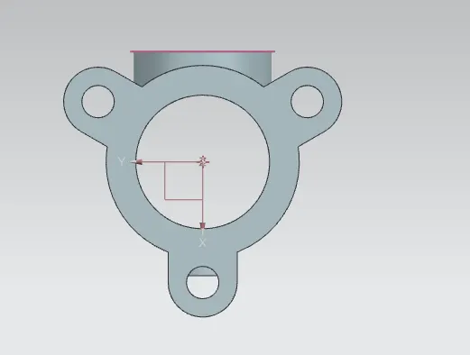
Butterfly valves are usually fixed between two pipleines using flange couplings. Body of our Butterfly valve and GD&T applied to the same using Siemens NX CAD are shown below.
- SHAFT - BUTTERFLY VALVE
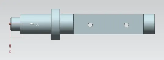
The disc/plate, lever and nut are assembled to this shaft.
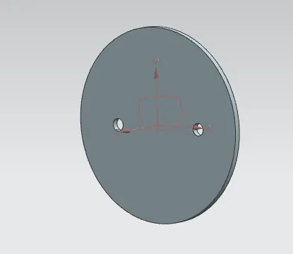
- DISC - BUTTERFLY VALVE
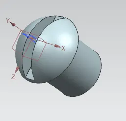
When valve is fully opened or closed the disc is rotated a quarter turn.Disc is mounted on shaft. When the valve is closed, the disc is turned so that it completely blocks off the passageway.When the valve is fully open, the disc is rotated a quarter turn so that it allows an almost unrestricted passage of the fluid.
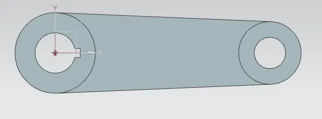
- LEVER - BUTTERFLY VALVE
Lever is mounted at an end of shaft outside the body. Hand lever is usually used in small sized Butterfly valves. It is used to open or close the valve.
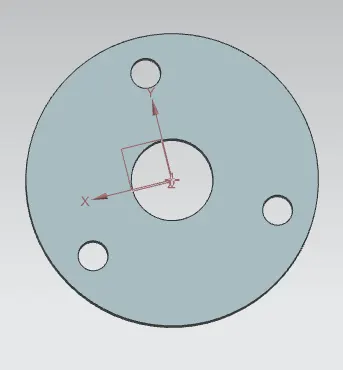
- RETAINER - BUTTERFLY VALVE
Retainer is a kind of washer fixed on the body of butterfly valve.
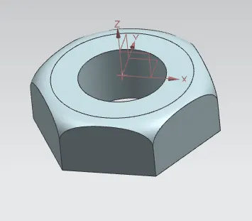
- NUT - BUTTERFLY VALVE
It is fixed at the top end of shaft to keep the lever and retainer on position relative to the body of butterfly valve.
7.Screw - BUTTERFLY VALVE
It is fixed disc and retainer on position relative to the body of butterfly valve.
ASSEMBLY - BUTTERFLY VALVE
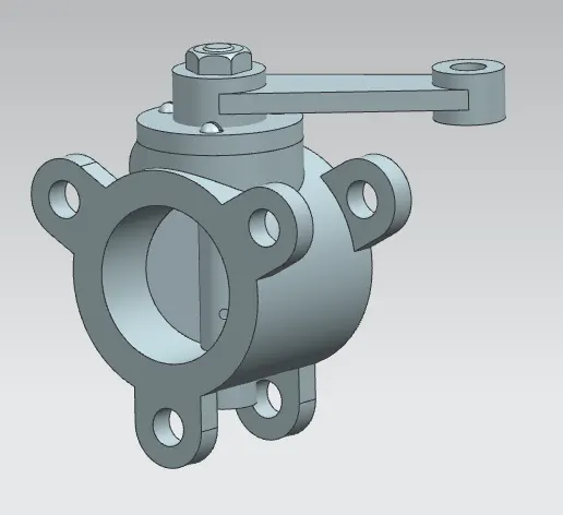
After completing the modelling of various components of butterfly valve, all parts were assembled together using Siemens NX Assembly workbench.
GD&T FOR ASSEMBLY: