Week 14 challenge
GEOMETRIC DIMENSIONING AND TOLERANCING (GD&T) FOR BUTTERFLY VALVE USING – ‘SIEMENS NX CAD’
OBJECTIVE:
The main objective of this project is to design the parts required for butterfly valve and its assembly, and applying geometric dimensioning and tolerancing to the assembled butterfly valve using the – “Siemens NX CAD” software.
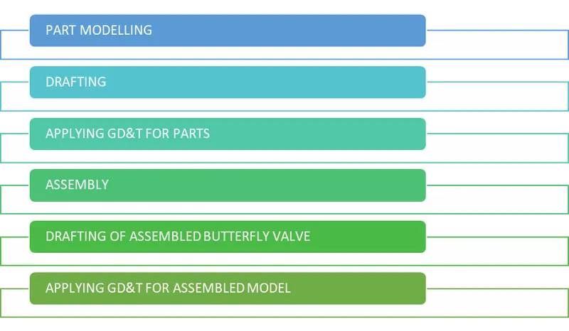
PROCESS PLAN:
DESCRIPTION:
Butterfly valve:
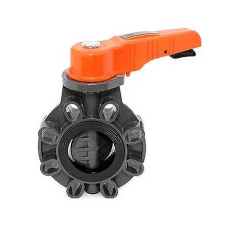
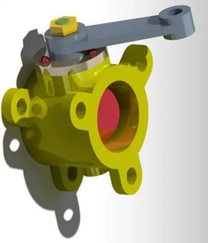
A butterfly valve is a valve that isolates or regulates the flow of a fluid. The closing mechanism is the disk that rotates.
Geometric dimensioning and tolerancing (GD&T):
Geometric Dimensioning and Tolerancing (GD&T) is a system for defining and communicating engineering tolerances and relationships. It uses a symbolic language on engineering drawings and computer-generated three-dimensional solid models that explicitly describe nominal geometry and its allowable variation. It tells the manufacturing staff and machines what degree of accuracy and precision is needed on each controlled feature of the part. GD&T is used to define the nominal (theoretically perfect) geometry of parts and assemblies, to define the allowable variation in form and possible size of individual features, and to define the allowable variation between features.
- Dimensioning specifications define the nominal, as-modelled or as-intended geometry. One example is a basic dimension.
- Tolerancing specifications define the allowable variation for the form and possibly the size of individual features, and the allowable variation in orientation and location between features. Two examples are linear dimensionsand feature control frames using a datum references (both shown below).

There are several standards available worldwide that describe the symbols and define the rules used in GD&T. One such standard is American Society of Mechanical Engineers (ASME) Y14.5-2009.
The important terms of geometric dimensioning and tolerancing (GD&T):
- Feature control frame
- Datums and datum references
- Symbols
- Feature control frame:
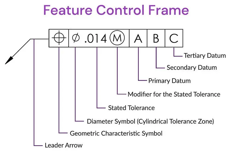
A feature control frame is used in GD&T to describe the conditions and tolerances of a geometric control on a part’s feature. The feature control frame consists of four main pieces of information:
- GD&T symbol or control symbol
- Tolerance zone shape and dimensions
- Tolerance zone modifiers: material condition modifiers, projections…
- Datum references(if required by the GD&T symbol).
- Datums and Datum references:
A datum is a virtual ideal plane, line, point, or axis. A datum feature is a physical feature of a part identified by a datum feature symbol and corresponding datum feature triangle. These are then referred to by one or more ‘datum reference’ which indicate measurements that should be made with respect to the corresponding datum feature.

An engineering datum used in geometric dimensioning and tolerancing is a feature on an object used to create a reference system for measurement. In engineering and drafting, a datum is a reference point, surface, or axis on an object against which measurements are made.
These are then referred to by one or more 'datum references' which indicate measurements that should be made with respect to the corresponding datum feature.
In geometric dimensioning and tolerancing, datum reference frames are typically 3D. Datum reference frames are used as part of the feature control frame to show where the measurement is taken from. A typical datum reference frame is made up of three planes. For example, the three planes could be one "face side" and two "datum edges". These three planes are marked A, B and C, where A is the face side, B is the first datum edge, and C is the second datum edge. In this case, the datum reference frame is A/B/C. A/B/C is shown at the end of feature control frame to show from where the measurement is taken.
- Symbols:
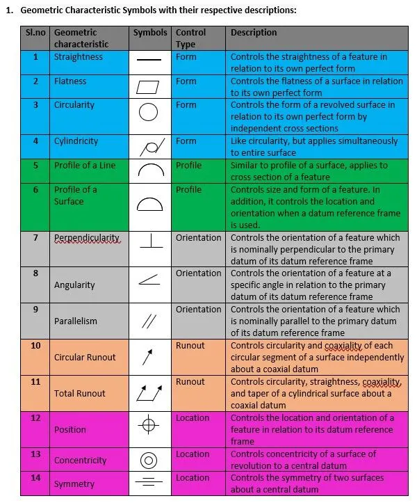
There are certain symbols used in geometric dimensioning and tolerancing to specify the geometric characteristic of the features. These symbols are present in the feature control frame to convey the actual position, size and modifiers of a particular features with respect to their datums.
Butterfly valve parts:
- Body
- Shaft
- Disc
- Retainer
- Lever
- Nut
- Screws
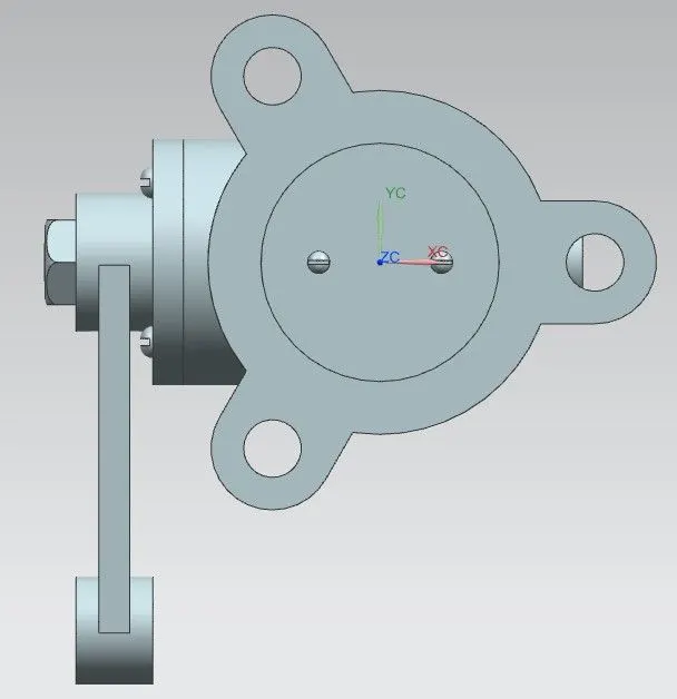
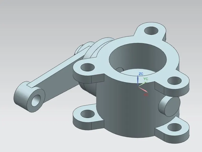
Body: It is the base part of butterfly valve, where the other parts are going to be assembled with. The design procedure for this part is simple- sketching the required shape in any plane, using the NX CAD features those 2D sketches are converted into 3D model with the help of Boolean operations and finally 2D drafting for the created part is done in drafting workbench of NX CAD.
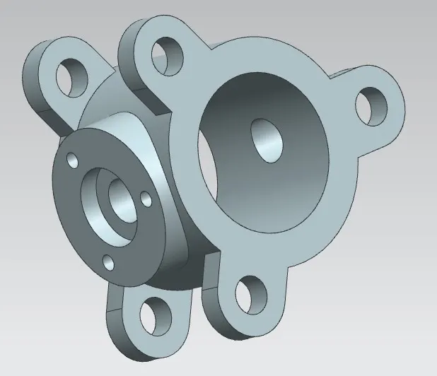
Body is shown in the above picture.
It is the base part so there is no need to apply GD&T.
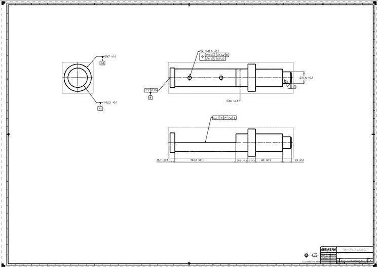
Shaft: It is the part which holds the disc at the centre of butterfly valve body and going to help to rotate the disc which controls the fluid flow, it also having a slot to place the key to align the lever with it. The design procedure for this part is same as before.
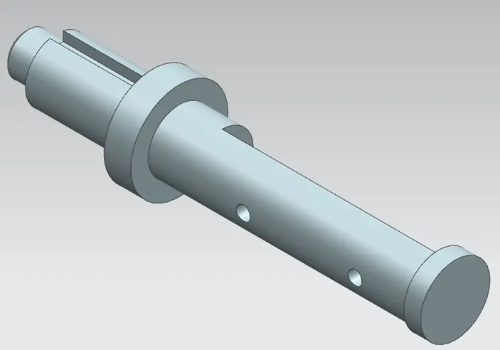
Shaft is shown in the above picture.
The required GD&T for the shaft is applied in the drafting workbench with the help of NX CAD features. The GD&T application starts with choosing the datum reference and then giving the geometric characteristic, tolerance size, tolerance zone shape and modifier (if required).
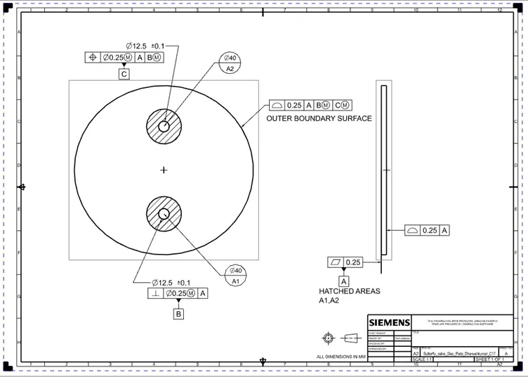
Disc: It is the part which is very important to isolate and regulates the flow of fluids in the butterfly valve. The disc is assembled to the shaft with help of screws. The design procedure is pretty much same as before.
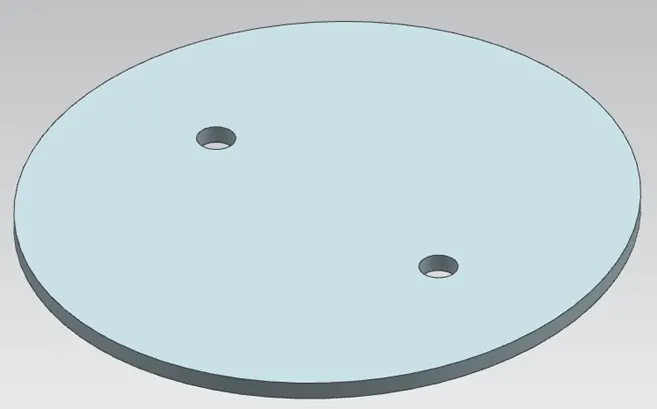
Disc is shown in the above picture.
The application of GD&T also same as before and it is applied to the disc part in drafting sheet.
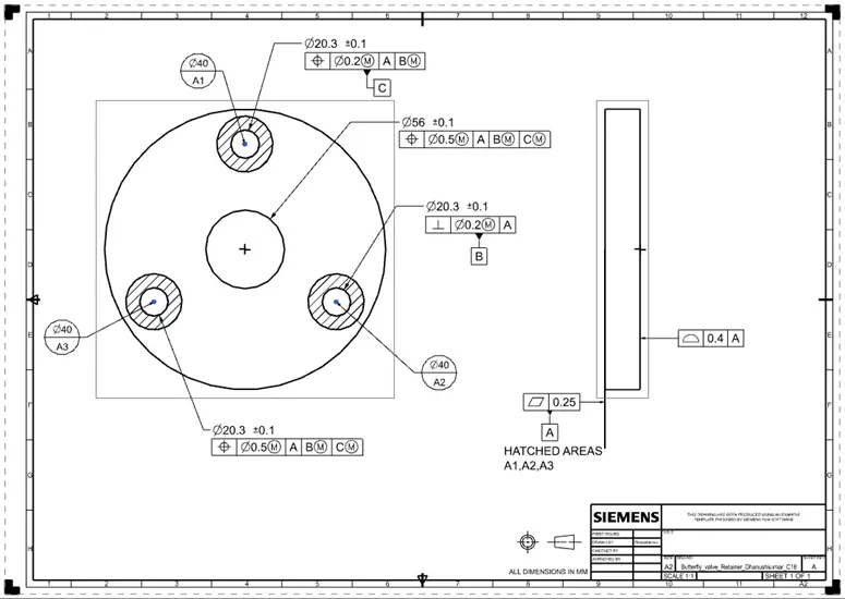
Retainer: It is the part which is assembled above the body after inserting the shaft to retain the sub-assembly of shaft and disc at its position in the butterfly valve. Again the design procedure for retainer is also same as before.
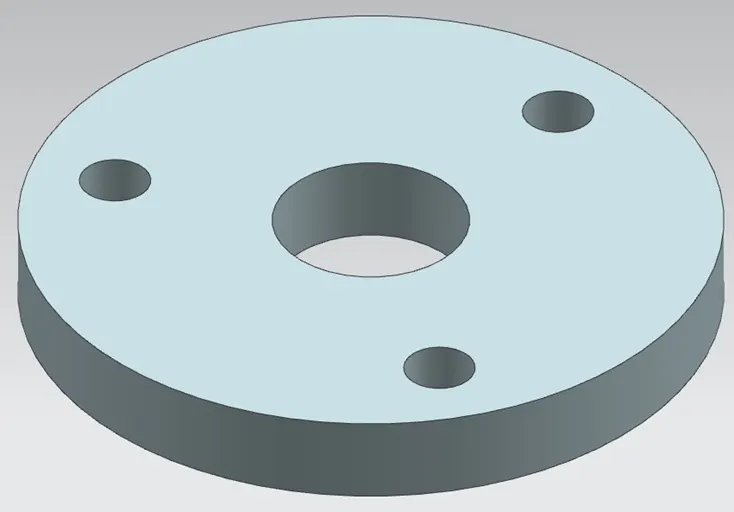
Retainer is shown in the above picture.
The application of GD&T also same as before and it is applied to the retainer part in drafting sheet.
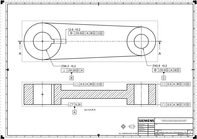
Lever: It is the part which is going to incorporate with the shaft, to help us to operate the valve by rotating it. Lever part is going to assembled over the retainer and around the shaft. The design procedure is same as before.
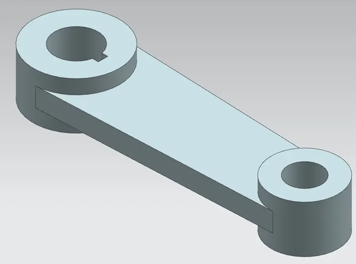
Lever is shown in the above picture.
The application of GD&T also same as before and it is applied to the lever part in drafting sheet.
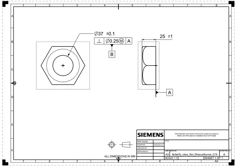
Nut: It is the final part of butterfly valve which is used to hold the lever in its position by having bolted with the shaft. Same design procedure is used to design the nut.
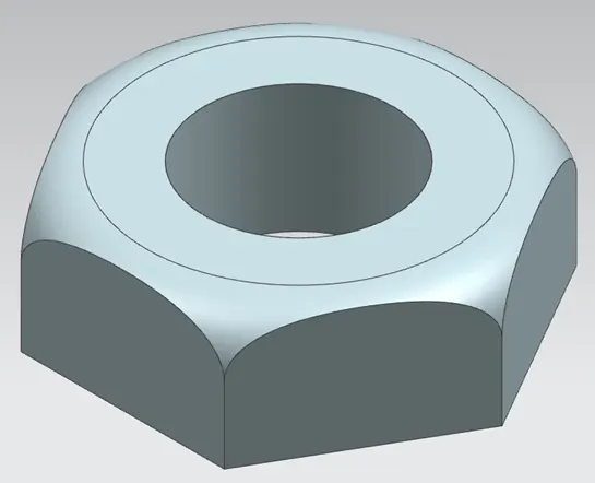
Nut is shown in the above picture.
The application of GD&T also same as before and it is applied to the nut part in drafting sheet.
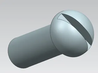
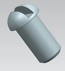
Screws: It is used to fasten the disc with shaft and retainer with body in the butterfly valve.
Assembly:
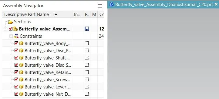
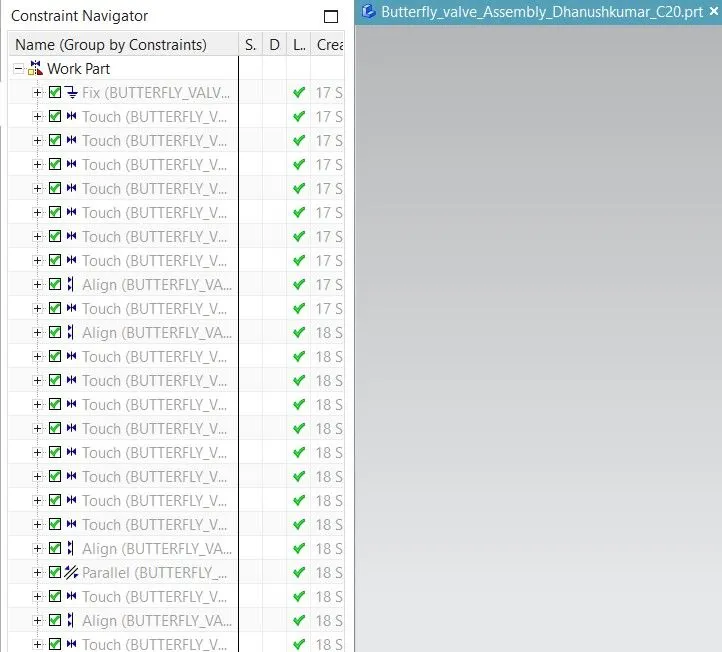
All the parts were designed before was opened in the assembly window of NX CAD to assemble them by giving certain assembly constraints. The body part is fixed in the assembly work window first and then the following steps are carried out,
- The sub-assembly of shaft, disc and screws are done by applying align and touch constraints between the respected features.
- Then this sub-assembly is aligned with body by aligning the shaft axis and hole axis in the body. After alignment the outer surface of disc and inner surface of body is constrained with touch constrain.
- The retainer and their respected screws were assembled to the body, by following the same steps as before.
- Then the lever part is aligned with shaft by aligning the larger hole axis with the axis of shaft, then the opposite faces of key slots is constrained by parallel constraint, and finally the bottom surface of lever is touch constrained with upper surface of body.
- At last, nut is assembled at the top of butterfly valve with the help of align and touch constraint.
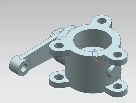
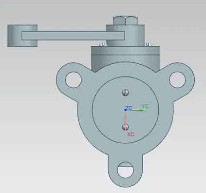
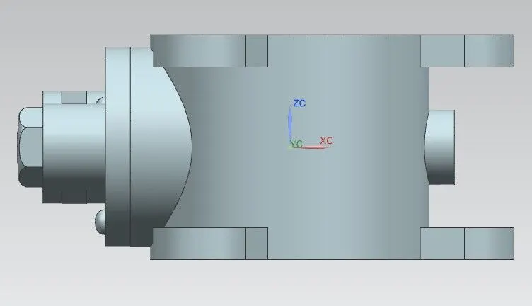
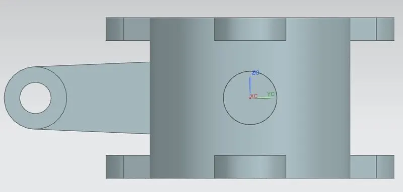
Assembled butterfly valve is shown in the above pictures.
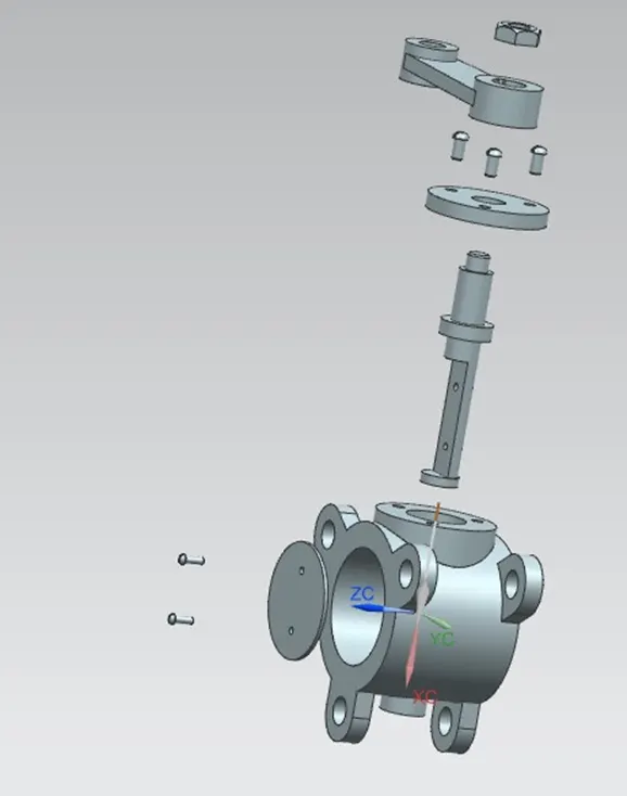
Exploded view of butterfly valve assembly is shown.
For the butterfly assembly, the following points are considered while applying the GD&T,
- The first surface which is going to contact with the external part is said to be the datum A because it arrests one translational and two rotational motions.
- Anyone screw hole or feature of size of the butterfly valve at the side of datum A is considered as our datum B because it is going to arrests two translational motions.
- Then according to the rules of GD&T, the far most feature of size is considered as our C datum and it arrests one rotational motion, now all the degrees of freedom where constrained.
- The remaining hole is given by an additional datum D as a reference to the hole which is parallel to it.
- The screw holes at the other side of butterfly valve should be co-axial with the datum B, C & D.
- The thickness of the butterfly valve is controlled by giving a profile of surface characteristic to surface parallel to the A datum.
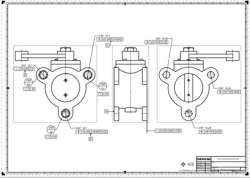
CONCLUSION:
The geometric dimensioning and tolerancing (GD&T), was applied to the assembled butterfly valve model according to the ASME Y 14.5 – 2009 standard using – ‘Siemens NX CAD’ software.