Week 14 challenge
Geometric Dimensioning and Tolerancing
BUTTERFLY VALVE – ASSEMBLY
Butterfly Valves are quarter-turn rotary valves in which a disc-shaped closure member is rotated through 90 degree or less to open or close or regulate the flow passage. Butterfly valves may be used for flow in both directions.
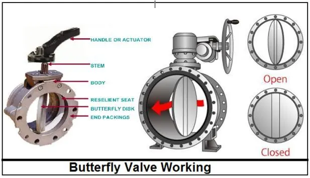
In operation, the valve is fully open or closed when the disc is rotated a quarter turn. The “butterfly” is a metal disc mounted on a rod. The disc is positioned in the center of the pipe. A rod passes through the disc to the outside of the valve. Rotating the rod, through hand-wheel or actuator, turns the disc either parallel or perpendicular to the flow.
When the disc plane is at right angle or perpendicular to the center line of pipe, butterfly valve is closed. Then when the disc is rotated a quarter turn to make the plane of disc in line with the center line of pipe, butterfly valve is fully open and it allows an almost unrestricted passage of the fluid. The valve may also be opened incrementally to throttle flow.
Butterfly Valve – ASSEMBLY
The Butterfly Valve Consists of the following main parts,
- BODY
- DISC
- STEM
- RETAINER RING
- HAND LEVER
- Butterfly Valve- Body
The body of the butterfly valve is the part that fits between the two pipes. This slim valve comes in two major body styles: wafer and lug. The wafer style body is the most economical of the two. It is connected to the pipes with bolt holes that run through the body of the valve. This design is easy to install and primarily used to prevent backflow in universal flow systems. However, it should be noted that they are not recommended for use in systems that require regulation.
Lug style butterfly valves are slightly more expensive than their counterpart but offer a few distinct advantages. Lug butterfly valves are connected to the pipe through protruding lug holes on the outside of the body of the valve. With this design, the valve actually helps carry the weight of the piping throughout its body, unlike the wafer valve. This allows for removing piping from one side of the valve for dead-end servicing.
- Butterfly Valve- Disc
Among different parts of butterfly valve, a disk exists that has been positioned inside the body of the butterfly valve. This disk is responsible to control the flow of the fluid and works similar to the gates or balls that are placed inside the ball valves. The disk also has two types: Eccentric and Concentric. The eccentric disc has a bit more complicated design compared to the concentric. The concentric disk contains a stem that passes through the disk’s centerline.
- Butterfly Valve- Stem
Although the stem is a very small item when compared to other parts of butterfly valve, it is crucial for the function of the valve. The stem is used for connecting the disk inside the valve to the handle that is positioned on the outside. It enables the butterfly valve to open or close.
- Butterfly Valve- Hand Lever
These parts are usually made from steel and they are chemically treated and powder coated to pass meticulous inspection/salt spray tests for dimensional accuracy. Hand levers commonly contain a handle and a locking lever. Plus, they are normally used for small butterfly valves. These hand levers can be locked into different positions including closed, open, and partially open.
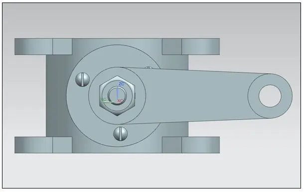
Assembly Views of BUTTERFLY VALVE
VIEW-1
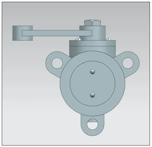
VIEW-2
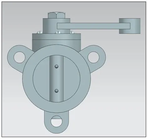
VIEW-3
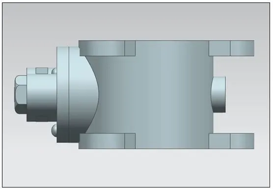
VIEW-4
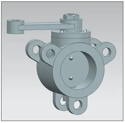
ISOMETRIC VIEW
Implementation of GD&T on BUTTERFLY VALVE ASSEMBLY
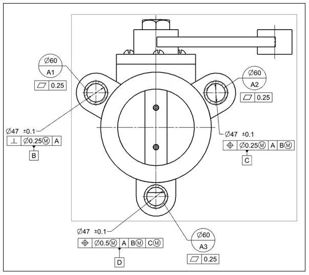
There are totally three Datum areas – Datum-A1, Datum-A2 and Datum-A3, which are present at the end connection of the valve body. The threed datum areas lie on the Datum plane-A.
A Flatness tolerance of 0.25 is provided for all the three Datum areas – A1, A2 and A3, which are lying on the Datum plane A.
Perpenciularity tolerance is considered for the hole of Datum area A1, which is limited to 0.25 at maximum material condition relative to Datum A and Datum B.
A position tolerance of 0.25 at maximum material condition is provided relative to Datum A and Datum B at MMC with respect to Datum C for Datum area A2
Another position tolerance of 0.5 at MMC is provided at Datum area A3 relative to Datum A and at MMC for Datum B and Datum C with respect to Datum D
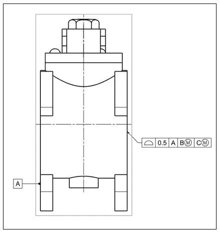
The Datum-A is the plane, where the three Datum areas lie (Datum-A1, A2 and A3)
A Profile tolerance of 0.5 is provided on the opposite base plane to Datum-A, relative to Datum- B and Datum-C at MMC.
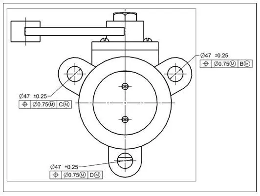
A position tolerance of 0.75 at maximum material condition is provided relative to Datum B at MMC for the hole on the opposite end of the valve body parallel to the hole of Datum area A1.
A position tolerance of 0.75 at maximum material condition is provided relative to Datum C at MMC for the hole on the opposite end of the valve body parallel to the hole of Datum area A2.
A position tolerance of 0.75 at maximum material condition is provided relative to Datum D at MMC for the hole on the opposite end of the valve body parallel to the hole of Datum area A3.