Week 12 - Symmetry vs Wedge vs HP equation
re=2100;
R=0.002;
D=2*R;
mu=0.89e-3;
L_e=0.06*re*D;
rho=997;
theta=45;
L=L_e+0.5;
vavg=(re*mu)/(rho*D);
vmax=2*vavg;
r=linspace(0,R,1000);
dp=(8*mu*L*vavg)/(R^2);
pk=(dp)/rho;
for i=1:length(r)
    tau(i)=(2*mu*vmax*r(i))/(R^2);
end
plot(r,tau)
xlabel('radial distance')
ylabel('shear stress')

header1='/*----------------------------------*- C++ -*------------------------------------*\'
header2='  =========                 |                                                                          '
header3='   \\      /  F ield                | OpenFOAM: The Open Source CFD Toolbox      '
header4='    \\    /   O peration        | Website:  https://openfoam.org                     '
header5='     \\  /    A nd                 | Version:  6                                                        '
header6='      \\/     M anipulation   |                                                                          '
header7='\*----------------------------------------------------------------------------------*/'

f1 = fopen('blockMeshDict','w')
fprintf(f1, '%s\n', header1)
fprintf(f1, '%s\n', header2)
fprintf(f1, '%s\n', header3)
fprintf(f1, '%s\n', header4)
fprintf(f1, '%s\n', header5)
fprintf(f1, '%s\n', header6)
fprintf(f1, '%s\n', header7)

fprintf(f1, 'FoamFile\n{\n')
fprintf(f1, '%12s \t 2.0;\n','version')
fprintf(f1, '%12s \t ascii;\n','format')
fprintf(f1, '%12s \t dictionary;\n','class')
fprintf(f1, '%12s \t blockMeshDict;\n','object')
fprintf(f1, '}\n')
header8='// * * * * * * * * * * * * * * * * * * * * * * * * * * * * * * * * * * * * * //'
fprintf(f1, '%s\n\n',header8)


fprintf(f1, 'convertToMeters 1;\n\n')

fprintf(f1, 'vertices\n')
fprintf(f1, '(\n')
fprintf(f1, '\t (%d  %d %d)\n',0,0,0)
fprintf(f1, '\t (%d  %d %d)\n',0,R*cosd(theta/2),R*sind(theta/2))
fprintf(f1, '\t (%d  %d %d)\n',0,R*cosd(theta/2),-R*sind(theta/2))
fprintf(f1, '\t (%d  %d %d)\n',L,0,0)
fprintf(f1, '\t (%d  %d %d)\n',L,R*cosd(theta/2),R*sind(theta/2))
fprintf(f1, '\t (%d  %d %d)\n',L,R*cosd(theta/2),-R*sind(theta/2))
fprintf(f1, ');\n\n')
fprintf(f1, 'blocks\n')
fprintf(f1, '(\n')
fprintf(f1, '\t hex (0 3 5 2 0 3 4 1) (%d %d %d)',400,40,1)
fprintf(f1, ' SimpleGrading (1 0.1 1)\n\n')
fprintf(f1, ');\n\n')
fprintf(f1, 'edges\n')
fprintf(f1, '(\n')
fprintf(f1, '\t arc %d %d (%d %d %d)\n',1,2,0,R,0)
fprintf(f1, '\t arc %d %d (%d %d %d)\n',4,5,L,R,0)
fprintf(f1, ');\n\n')
fprintf(f1, 'boundary\n')
fprintf(f1, '(\n')
fprintf(f1, '\t inlet \n')
fprintf(f1, '\t {\n')
fprintf(f1, '\t\t type patch;\n')
fprintf(f1, '\t\t faces\n')
fprintf(f1, '\t\t (\n')
fprintf(f1, '\t\t\t (0 1 2 0)\n')
fprintf(f1, '\t\t );\n')
fprintf(f1, '\t }\n')
fprintf(f1, '\t outlet\n')
fprintf(f1, '\t {\n')
fprintf(f1, '\t\t type patch;\n')
fprintf(f1, '\t\t faces\n')
fprintf(f1, '\t\t (\n')
fprintf(f1, '\t\t\t (3 5 4 3)\n')
fprintf(f1, '\t\t );\n')
fprintf(f1, '\t }\n')
fprintf(f1, '\t top\n')
fprintf(f1, '\t {\n')
fprintf(f1, '\t\t type wall;\n')
fprintf(f1, '\t\t faces\n')
fprintf(f1, '\t\t (\n')
fprintf(f1, '\t\t\t (1 4 5 2)\n')
fprintf(f1, '\t\t );\n')
fprintf(f1, '\t }\n')
fprintf(f1, '\t front\n')
fprintf(f1, '\t {\n')
fprintf(f1, '\t\t type symmetry;\n')
fprintf(f1, '\t\t faces\n')
fprintf(f1, '\t\t (\n')
fprintf(f1, '\t\t\t (0 3 4 1)\n')
fprintf(f1, '\t\t );\n')
fprintf(f1, '\t }\n')
fprintf(f1, '\t back\n')
fprintf(f1, '\t {\n')
fprintf(f1, '\t\t type symmetry;\n')
fprintf(f1, '\t\t faces\n')
fprintf(f1, '\t\t (\n')
fprintf(f1, '\t\t\t (0 2 5 3)\n')
fprintf(f1, '\t\t );\n')
fprintf(f1, '\t }\n')
fprintf(f1, '\t axis\n')
fprintf(f1, '\t {\n')
fprintf(f1, '\t\t type empty;\n')
fprintf(f1, '\t\t faces\n')
fprintf(f1, '\t\t (\n')
fprintf(f1, '\t\t\t (0 3 3 0)\n')
fprintf(f1, '\t\t );\n')
fprintf(f1, '\t }\n')
fprintf(f1, '); \n\n')
fprintf(f1, 'mergePatchPairs\n')
fprintf(f1, '(\n')
fprintf(f1, ');\n')
header9='// * * * * * * * * * * * * * * * * * * * * * * * * * * * * * * * * * * * * * //'
fprintf(f1, '%s\n',header9)
fclose(f1)
The above code is written for different wedge angles at symmetry boundary conditions. The boundary conditions for pressure and U fields were also changed to symmetry before running the simulation. The above code is written for wedge angle of 45 degree and theta was changed accordingly as given in the problem statement.
45 degrees:
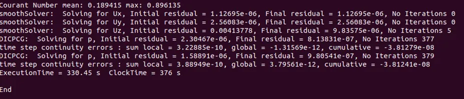
max CFL number =0.896
execution time 330.45 seconds
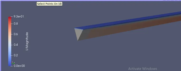
this shows the velocity contour on 45 degree wedge angle which has max velocity of 0.937m/s.
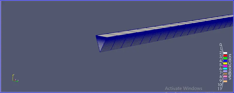
this shows the mesh on 45 degree wedge.
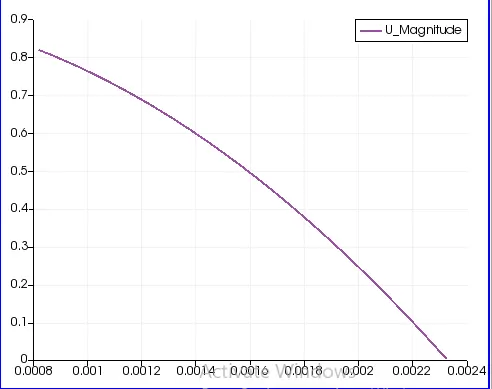
the above shows the velocity profile for wedge angle 45 degree.
25 degree:

max CFL number:0.878
execution time: 329.4 seconds
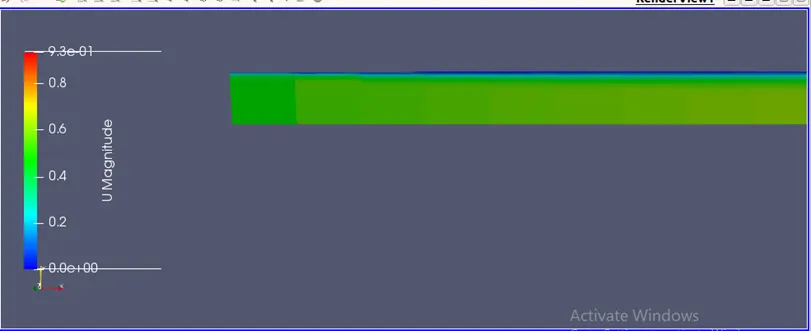
velocity contour for 25 degree.
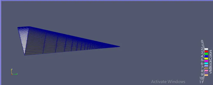
this shows the mesh profile for 25 degree wedge angle.
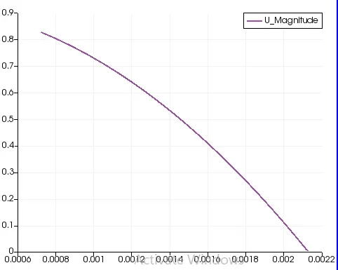
velocity profile for wedge angle 25 deg at x=0.6
10 degree:
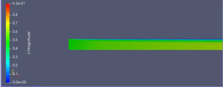
velocity contour for 10 degree wedge angle.
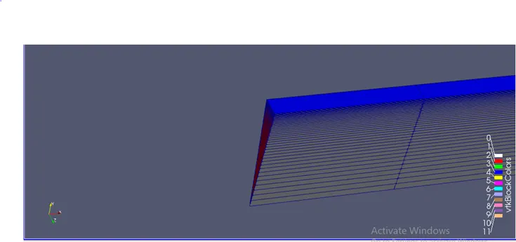
mesh profile for 10 deg wedge angle.

max CFL number=0.8711
execution time:318.95
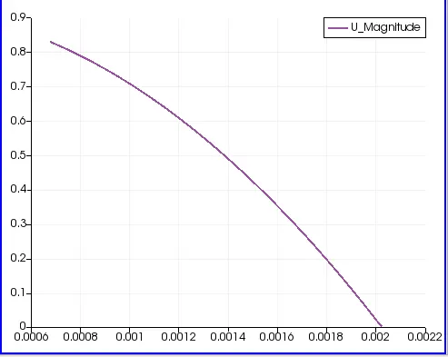
velocity profile for 10 deg wedge angle at x=0.6m
4degree wedge boundary condition simulation:

CFL max number :0.8712
execution time: 299.79 seconds .
This shows that for wedge boundary conditions the execution time is less as compared to the symmetry boundary conditons.
and the above results also show that with increasing wedge angle ther is not much change in max velocity or velocity profile but a slight change in CFL number and execution time in creases with wedge angle. also the cfl number increases with wedge angle.
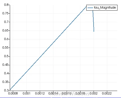
now for shear stress the analytical solution is calculated by hagen poiseulli equation:
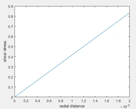
this is the analytical solution.
now after post processing in parafoam we get the shear stress plot as: