Week 12: Shell and Tube Heat Exchanger simulation
Shell and Tube Heat Exchanger simulation
Aim:
Aim: The objective of this simulation example is to analyze the heat transfer in a shell and tube heat exchanger configuration.
The heat exchanger can also be classified based on flow arrangement which is as follows:
- Double pipe parallel-flow heat exchanger
- Double pipe counter flows heat exchanger.
- Crossflow heat exchanger.
Geometry:
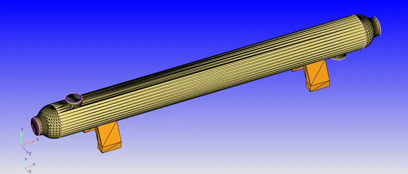
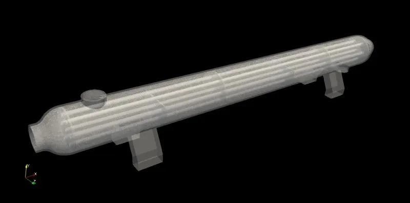
The geometry was imported into Converge and cad clean up was done. After fixing all the errors & the boundaries were flagged & the case was set up.
Shell & Tube Heat exchanger
Case Setup:
- Application: General Flow
- Solver: Transient solver
- Simulation Type: GAS & Liquid
- Fluid Material:
- Species on Shell side Fluid is: Ethylene Glycol Oil (C2H6O2) this is hot fluid
- Species on Tube side Fluid is Water (H2O) this is cold fluid
- Solid Material: Copper
- Simulation mode: Full hydrodynamic
- Simulation time parameters:
Start time:0 sec
End time: 1.5 sec - Region & Initialization:
In this step, we have created a region of the fluid. - Turbulence model:k-epsilon
- Super cycling was done
- Grid Control:
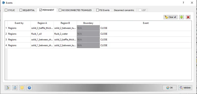
Element size:dx, dy & dz =0.01m - Events:
We have created the following permanent events.
Plots for Parallel flow are as follows:
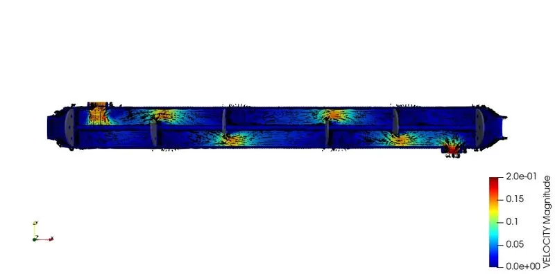
Velocity:
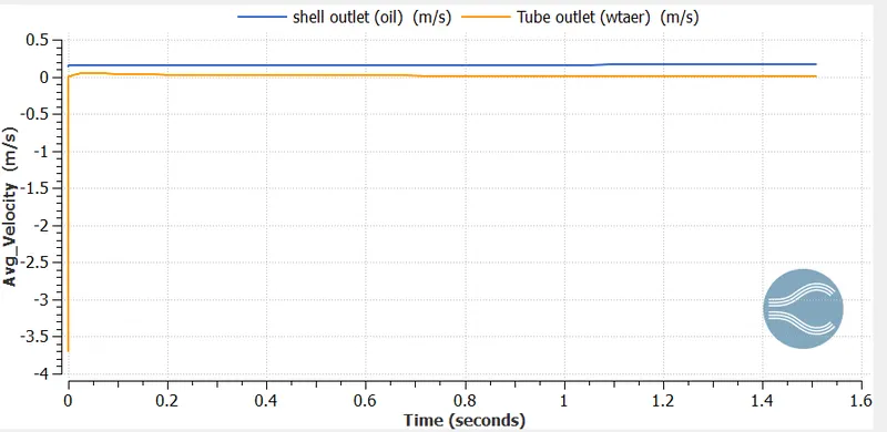
From the above plot:
- Velocity of Cold fluid (v_c)=0.019m/s
- Velocity of Hot fluid (v_h)=0.146m/s
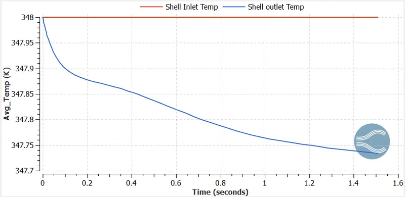
Shell Side Temperature:
Tube side Temperature:
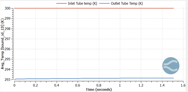
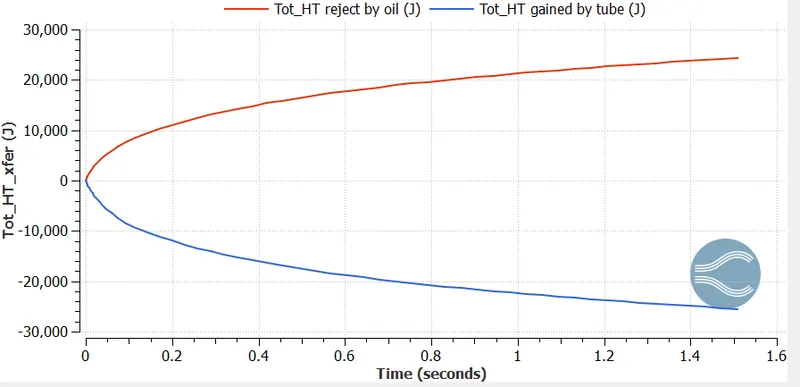
Total Heat transfer between oil and tube:
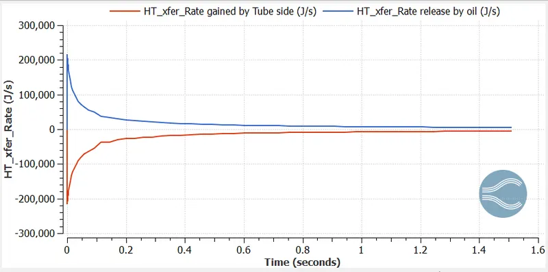
Heat transfer rate between oil and tube:
Calculation:
Given Data:
Tube side fluid à Water (H2O) à COLD FLUID
- Temperature of cold fluid at inlet (T_ci) = 20° C
- Temperature of hot fluid at inlet (T_hi) = 75° C
- Outer Diameter of Tube(d_o) = 23 mm
- Inner Diameter of Tube (d_i) = 20 mm
- h_i = 4500 W/(m^2-K)
- h_o = 1250 W/(m^2-K)
- Length of tubes (l) = 2.4 m
- C_(p(H2O)) = 4200 J/(Kg-K)
- C_(p(C2H6O2)) = 2600 J/(Kg-K)
- Number of tubes (n) = 7 tubes
- Mass flow rate of cold fluid = 1.162 kg/s
- Mass flow rate of hold fluid = 1.252 kg/s
To Find:
LMTD (Log Mean Temperature Difference)
From data:
Tci=20oCTci=20oC & Thi=75oCThi=75oC
From above Temperature plot:
Tco=27oCTco=27oC & Tho=74.7oCTho=74.7oC
At Inlet:
ΔT=Thi−TciΔT=Thi-Tci
ΔTi=75−20=55oCΔTi=75-20=55oC
At Outlet:
ΔT=Tho−TcoΔT=Tho-Tco
ΔTo=74.7−27=47.7oCΔTo=74.7-27=47.7oC
LMTD
ΔTm=ΔTi−ΔToln(ΔTiΔTo)ΔTm=ΔTi-ΔToln(ΔTiΔTo)
ΔTm=55−47.7ln(5547.7)ΔTm=55-47.7ln(5547.7)
ΔTm=51.26oCΔTm=51.26oC
Heat Transfer Rate:
Q=mh×Ch×dthQ=mh×Ch×dth
Q=1.252×2600×(75−74.7)=976.56WQ=1.252×2600×(75-74.7)=976.56W
Formula:
Q=UoAsΔTmQ=UoAsΔTm
976.56=Uo×π×do×n×L×51.26976.56=Uo×π×do×n×L×51.26
Uo=15.69Wm2KUo=15.69Wm2K
Geometry:
- Velocity Contour:
Plots for Counter flow are as follows:
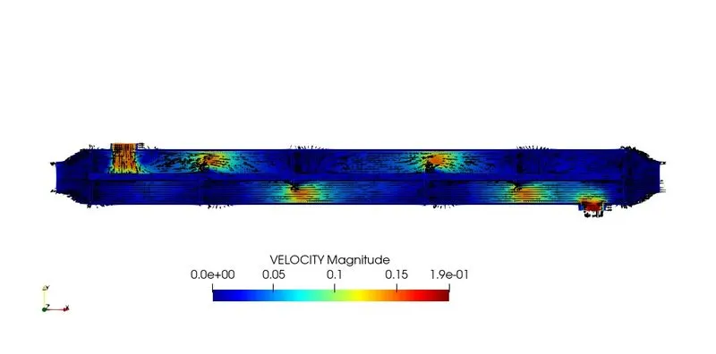
Velocity:
From the above plot:
- Velocity of Cold fluid (v_c)=0.019m/s
- Velocity of Hot fluid (v_h)=0.146m/s
Shell Side Temperature:
Tube side Temperature:
Total Heat transfer between oil and tube:
Heat transfer rate between oil and tube:
Calculation:
Given Data:
Tube side fluid à Water (H2O) à COLD FLUID
- Temperature of cold fluid at inlet (T_ci) = 20° C
- Temperature of hot fluid at inlet (T_hi) = 75° C
- Outer Diameter of Tube(d_o) = 23 mm
- Inner Diameter of Tube (d_i) = 20 mm
- h_i = 4500 W/(m^2-K)
- h_o = 1250 W/(m^2-K)
- Length of tubes (l) = 2.4 m
- C_(p(H2O)) = 4200 J/(Kg-K)
- C_(p(C2H6O2)) = 2600 J/(Kg-K)
- Number of tubes (n) = 7 tubes
- Mass flow rate of cold fluid = 1.162 kg/s
- Mass flow rate of hold fluid = 1.252 kg/s
To Find:
LMTD (Log Mean Temperature Difference)
From data:
Tci=20oCTci=20oC & Thi=75oCThi=75oC
From above Temperature plot:
Tco=27oCTco=27oC & Tho=74.7oCTho=74.7oC
At Inlet:
ΔT=Thi−TciΔT=Thi-Tci
ΔTi=75−20=55oCΔTi=75-20=55oC
At Outlet:
ΔT=Tho−TcoΔT=Tho-Tco
ΔTo=74.7−27=47.7oCΔTo=74.7-27=47.7oC
LMTD
ΔTm=ΔTi−ΔToln(ΔTiΔTo)ΔTm=ΔTi-ΔToln(ΔTiΔTo)
ΔTm=55−47.7ln(5547.7)ΔTm=55-47.7ln(5547.7)
ΔTm=51.26oCΔTm=51.26oC
Heat Transfer Rate:
Q=mh×Ch×dthQ=mh×Ch×dth
Q=1.252×2600×(75−74.7)=976.56WQ=1.252×2600×(75-74.7)=976.56W
Formula:
Q=UoAsΔTmQ=UoAsΔTm
976.56=Uo×π×do×n×L×51.26976.56=Uo×π×do×n×L×51.26
Uo=15.69Wm2KUo=15.69Wm2K
Geometry:
Velcoity Contour:
Drawbacks of shell and tube heat exchanger:
- Heat exchanger effectiveness is less.
- Cleaning and maintenance are troublesome since a tube cooler requires enough clearance at one end to remove the tube nest.
- The capacity of the tube cooler cannot be increased.
- Requires more space in comparison to plate coolers
Fouling factors: We know the surface of the heat exchangers do not remain clean after it has been in use for some time. The surface becomes fouled with scaling or deposits. The effects of these deposits affecting the value of the overall heat transfer co-efficient. This effect is taken care of by introducing an additional thermal resistance called fouling resistance.
CONCLUSION:
So, the simulation process of shell and tube heat exchanger is done with both counter and parallel flow. The results show that the counter flow is better than the parallel flow.