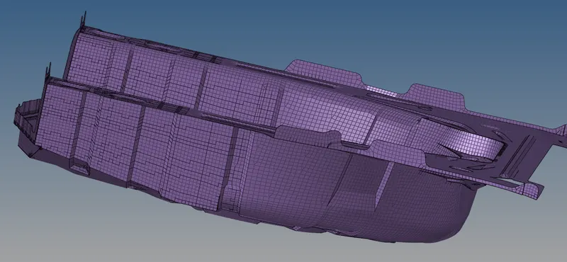
Week 12:Project 2-Meshing of Rear Wheel Holder challenge
Meshing of Trunk Floor Pan
OBJECTIVE:
To pre-process the given wheel holder geometry by performing topology optimization, mid surface extraction and finally surface meshing and mesh refinement.
INTRODUCTION
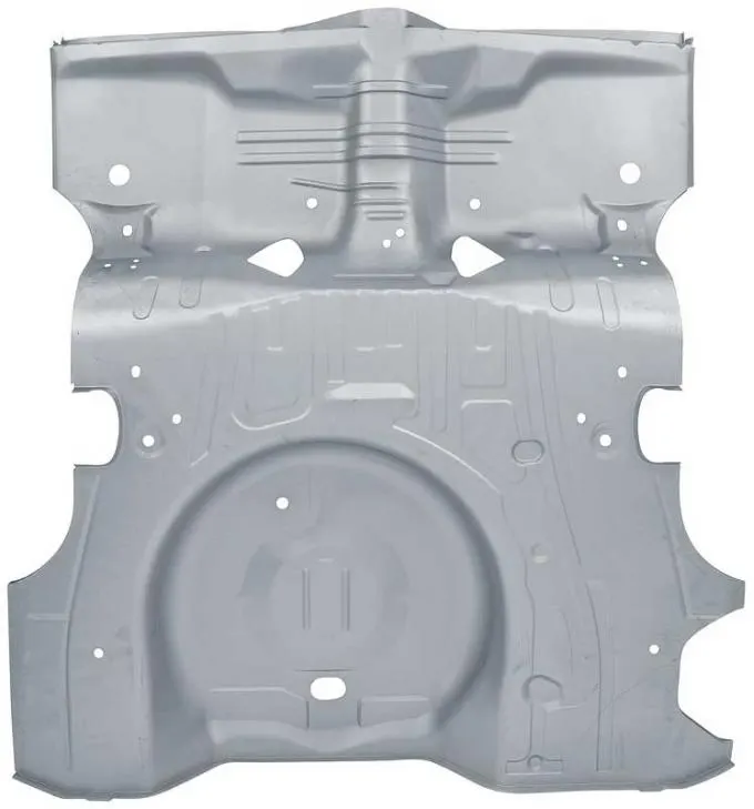
Rear wheel floor pans are large sheet metal stamping subcomponents that are present inside the trunk of a car and welded directly to the chassis of the automobile. The floor pan in the trunk is used to accommodate space for holding the spare wheel of an automobile/
Below is shown the rear floor pan of a mustang
PROCEDURE:
Geometry cleanup
- Import the geometry model using the import option.
- The model is set to topo visualization to visualize the free edge, shared edges, triple shared etc..
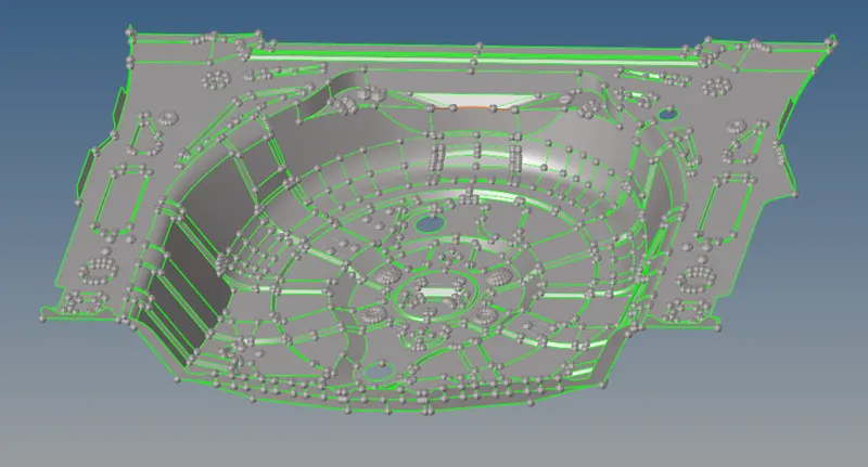
- Cleanup the geometry either using automatic or manual methods. The auto method involves the autocleanup command.
- However since very few free edges are present at shared surfaces i.e they are not stiched. Hence manual cleanup can be performed using the toggle command, equivalence, surface create, delete, etc.
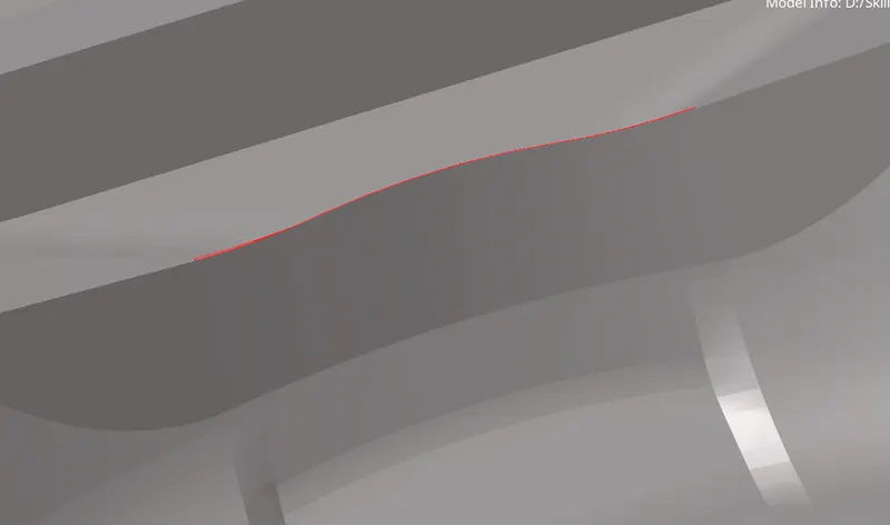
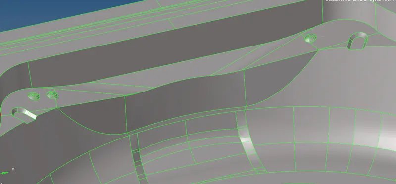
- Prior to extracting the mid, it can be noticed that the main component and most of it all lie on a single component part. Hence using the organize option we can move all these existing surfaces onto the main single component.
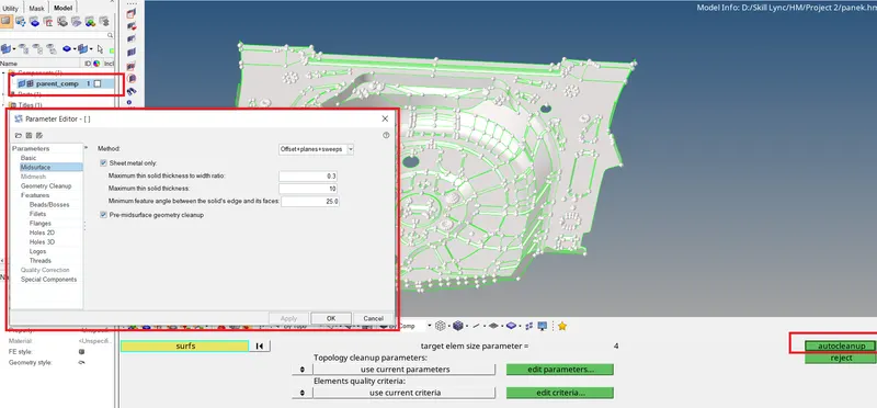
- Even after performing a manual cleanup, it is advisable to perform auto mid cleanup using the autocleanup command so that the hypermesh algo can defeature certain features. This can then be rechecked and rectified by the user manually.
- Moreover this autcleanup command can also perform a mid surface extraction, mid mesh or surface mesh with a mid component. In our case, the mid extraction process is also checked on to see if hypermesh could give a appropriate result.
Mid-surface extraction
- In most cases, even the autocleanup feature fails to extract the mid of the component if it is intricate and complex. However it does defeature unrequired features.
- To extract the mid using an alternative command we make use of the midsurface command in the Geom module.
- The mid surface extracted using automatic method is shown below
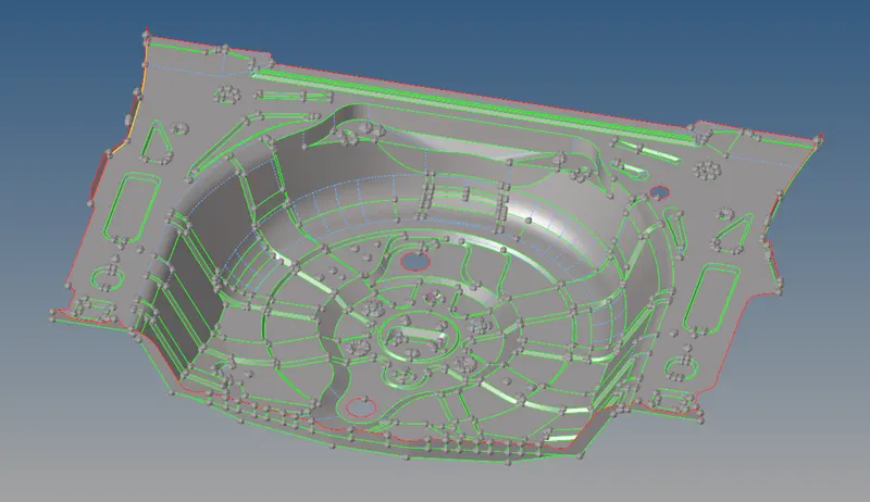
- While the mid seems to be perfect, there are many unstictched features. These must be manually corrected using the toggle command, equivalence, surface create, delete, etc.
- Also features are checked at each area and corrected by defeaturing since the algo during autocleanup dosent capture a feature by defeaturing rather it defeatures those that are present close to adjacenet features.
- While most feature have been captured perfectly using hypermesh autcleanup method, this method failed to capture the semicircular peak features and other extruded small fillet features. Hence these can either be toggled or deleted entirely and rebuilded
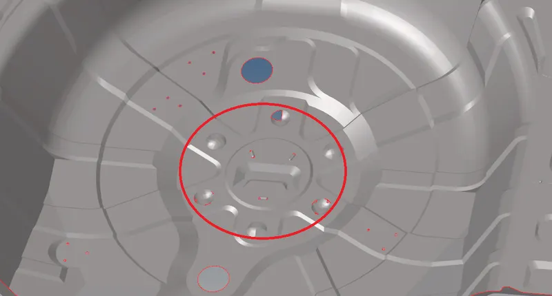
- Also the presence of beads would abrupt the occurance of a smooth mesh flow. Hence these beads can be deleted and the holes that pertain and remain after bead deletion can be closed by creating a new surface.
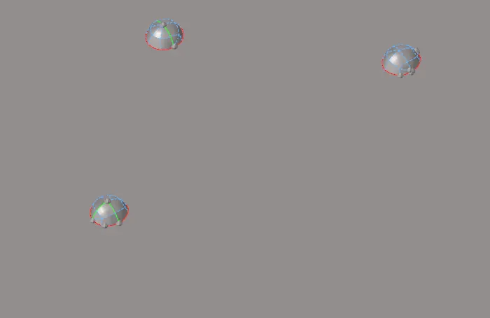
- Similarly other bead like features and small extruded fillets are deleted from the flat surface hence to achieve a smooth mesh flow.
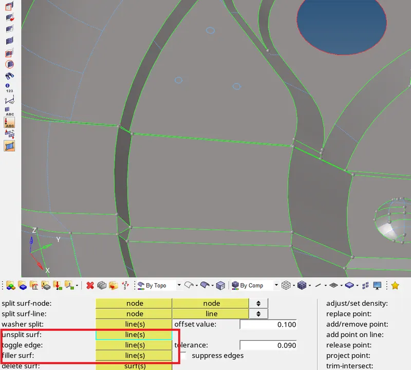
- Beads that remain as hole in the flat surface can be fillet using filler surf in the quick edit tab and then toggled to defeature these hole perimeter lines. Or using un-split option. They both provide the same result
- While the mid surface of larger beads around the centre of the part is distorted due to the automid extraction, hence these features can either be capture for its perfect perimeter and recreated or if a single feature is capture perfectly then this feature can be transformed.
- To transform (rotate) a single part about a neutral axis:
- Delete the distorted surfaces
- Create a mid point of the arc/circule from the nodes menu
- Select the perfect feature for the roation operation
- Select the axis of rotation (z-axis) and the base point
- Calculate the angle of rotation (360/3 = 120)
- Duplicate the component and rotate it (as shown below)
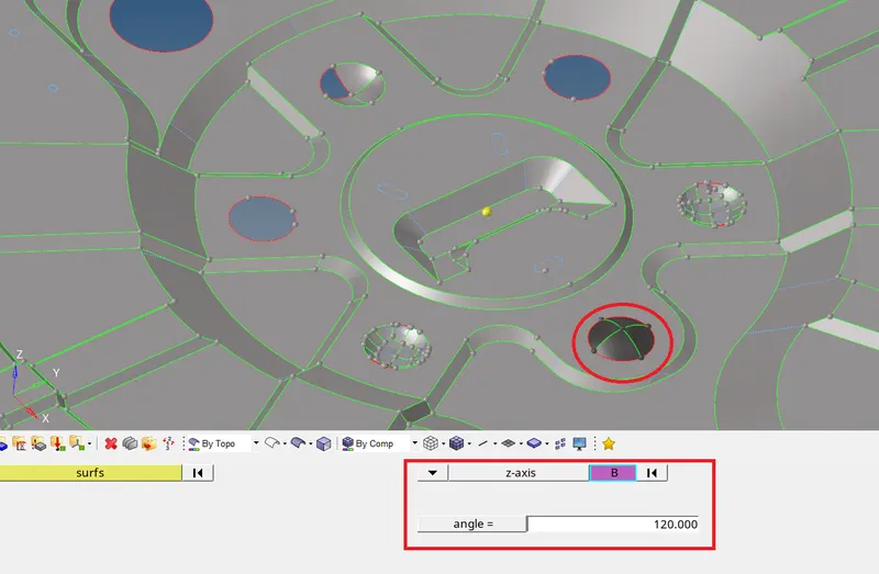
- After rotating the duplicate components. To attain connectivity, toggle the edges.
- Similarly the same is translated to a 180 degree i.e upside down and then rotated to the other 3 places using the rotation option.
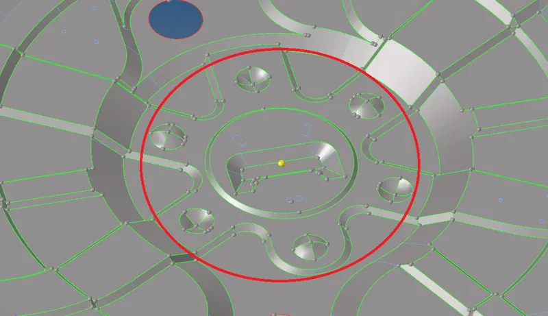
Meshing & Refinement
- Before meshing the component the quality parameters are set under the criteria file setting.
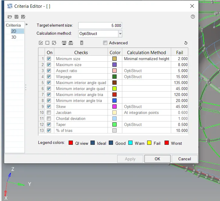
- Mesh can be generated either all at one shot or by selecting surface by surface. The former gives a coarse mesh without proper mesh flow. Hence the latter is preferred.
- To mesh such a intricate and complex part would be difficult. Hence the symmetry of the model can be took as an advantage where we can model and mesh only half of the component and reflect it to the opposite side.
- The given model consists of few features that are symmetrical about an axis while few other features arent symmetrical. Hence we can mask off those that are unsymmetrical and use the left out region to mesh half of it and reflect it.
- The symmetrical part of the model is shown below.
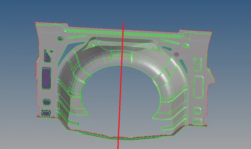
- Even among the components that are remaining (unmasked) a few portions and certain features are still arent symmetrical. Hence these feature can also be masked and meshed later seperately.
- From the remainng unmasked component those feature that are symmetrical can be meshed individuall and reflected about the central point.
- To reflect the model, a symmetrical plane has to be created to seperate the two opposite sides. To do this a surface trim oprtation is performed using the mid point on the component.
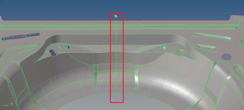
- To keep elems failing for min mesh size, small fillets are either defeatured by its entire surface or edge lines only.
- Finally all symmetrica features from the model have been meshed and reflected as shown below
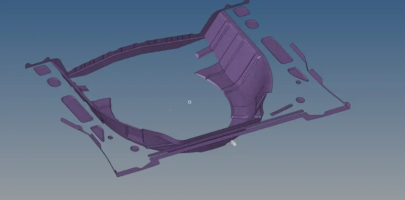
- Then the unsymmetrical features of the model are then meshed individually.
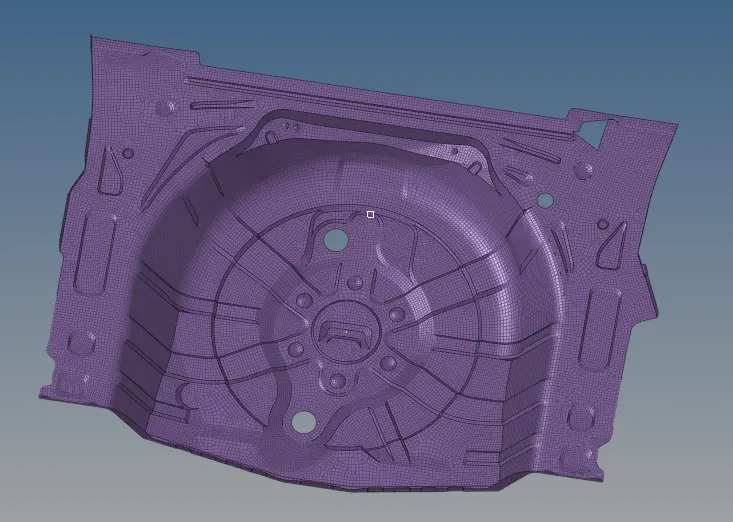
- Finally the meshed component is shown below
Assigning property card
- Before creating a property card, a new material card has to be created and assigned to the property card.
- To create a material card for steel
- Mat name=steel - type = ISOTROPIC - card image = MAT1
- MAT4 and MATF are used for thermal and fluid properties
- Other mechanical properties of the material like E, Poissons ratio, density etc are defined

- Property cards are created in a much similar way:
- Since the mid of the component has been extracted a PSHELL card pertaining to the thickness (original) of the component is created
- Required params: type = PSHELL, material = steel (previously created), t = 0.75

- Finally to visualize the thickness of the meshed component: The '2d detailed element representation' option is checked on.
CONCLUSION
Hence the given component was pre-processed by performing geometry cleanup, mid surface extraction and meshed using 2D elements.
The meshed component is displayed below along with its thickness.