Week 12:Project 2-Meshing of Rear Wheel Holder challenge
AIM
Follow the below-mentioned quality criteria, mesh the component given below and assign thickness:
Target Element Length = 5mm
| S.N | Quality Criteria | Value |
| 1 | Aspect Ratio | 5 |
| 2 | Skewness | 45 |
| 3 | Warping | 15 |
| 4 | Taper | 0.5 |
| 5 | Min. Length | 2mm |
| 6 | Max. Length | 8mm |
| 7 | Min angle Quad | 45 |
| 8 | Max angle Quad | 135 |
| 9 | Min angle Tria | 20 |
| 10 | Max angle Tria | 120 |
| 10 | Tria % | 10 |
Procedure
- Import the geometry and check for geometrical error which need to be corrected .
- Generate a mid surface by auto mid surface feature.
- Clean up the geometry for any kind of imperfect surfaces and unnecessary lines or points.
- After that mesh the component as per the quality criteria starting from one side of the surface to another side.
- After meshing the total component, assign the thickness as per the original parent geometry.
Step:1
The given component has beenimported into the hypermesh with Optistruct profile.
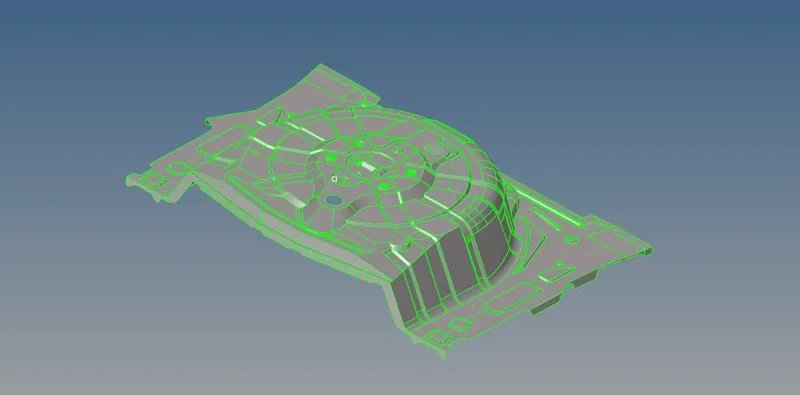
After that any solid from the surface is deleted from the components.

The given component has few igeometrical errors which are to be fixed manually so that to generate a perfect mid surface of the component.
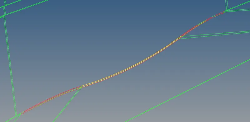
The given probelm can bee fixed by replacing the lines and using fillers surface which is present in quick edit submenu of Geometry toolbar.

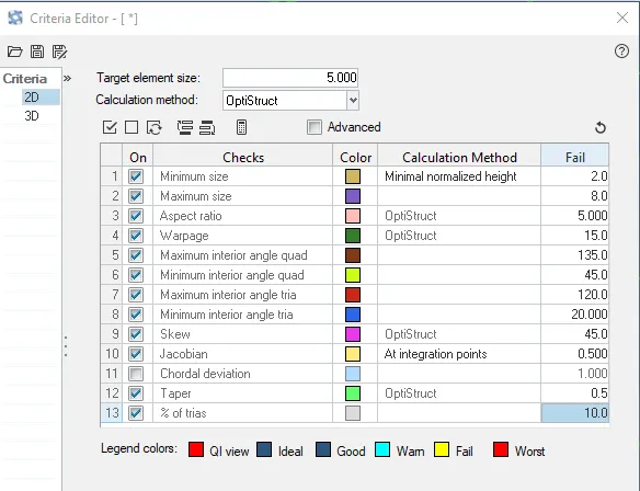
After geometry cleanup next ,to define the criteria file which is required by our model meshing.
Step 2:
After meshing next step is generate the midsurface for meshing.
Midsurface modeling is a technique for creating a simplified shell representation of a solid model.
Midsurface modeling can reduce the computational expense of analyzing a complete solid model when a shell model with a defined thickness and fewer details is suitable for the required analysis.
Midsurface gemeration by the Geometry toolbar provided in the hypermesh.

We have selected automidsurafe option with offset+planes+sweep midsurface option present with the model.
After midsurface we get the following components.
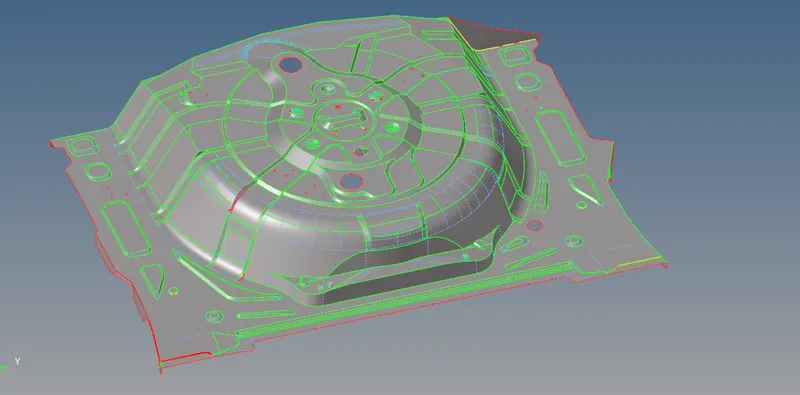
As the model generated has some geometry problem , we need to cleanup the mmidsurface before meshing the compoenets.
Step 3:
Next step is meshing the components.
Meshing is an integral part of the engineering simulation process where complex geometries are divided into simple elements that can be used as discrete local approximations of the larger domain.
The mesh influences the accuracy, convergence and speed of the simulation.
We have generated 2D mesh, for meshing.

After meshing we get the following components.
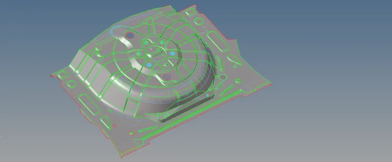
After meshing the components consists of bad elemens which doesn't meet the criteria.
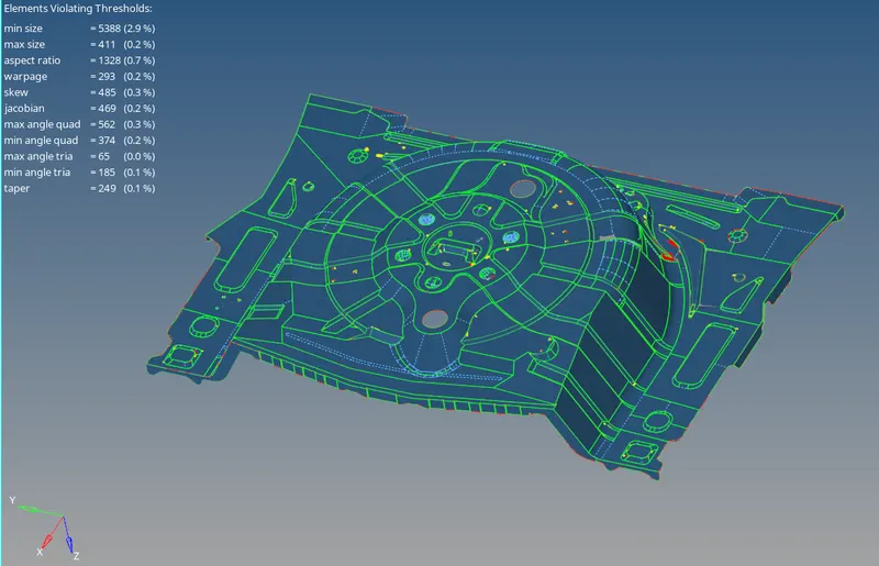
These elements need to be cleaned to get the requirement mesh criteria.
The failed elements can be fixed using the element fixing tools in the quality criteria menu.
While using the quality criteria menu the failed elements are highlighted in yellow and red colours.
Yellow errors indicate that the errors can be fixed easily, whereas the red colour indicates critical errors.
Results
After cleaning the elemnts consists of few bad elements its because of skewness at sharp corners which can't be cleaned.
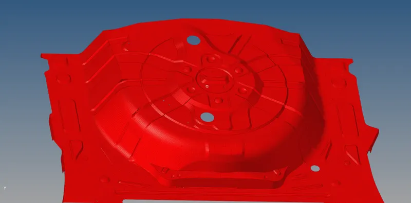
After that thickness is assigned to the components by creating the property card for the parts.
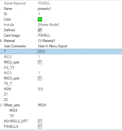
After creating the property this card is assigned to the componets which provide the desired thickness.
-----------------------------------------------------------------------------------------------------------------------------------------------------------
Conclusion
- Midsurface has been successfully extracted from the components and 2Dtetramesh has been successfully performed.
- After meshing thickness for the given components has been assigned with the help of property card created for the components.