Week 12:Project-1-Meshing of Door Inner Panel Challenge
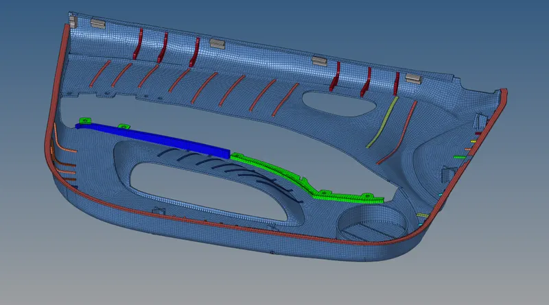
The meshing of Door Inner Panel
OBJECTIVE:
To perform pre-processing operations like Topology optimization, mid surface extraction and finally surface mesh generation on the Inner panel of a door model of an automobile using Hypermesh
PROCEDURE:
Topology optimisation
- The .hm model is opened from the hypermesh GUI. The Model visualization is set to Topo to visualize the free, shared edges in the model
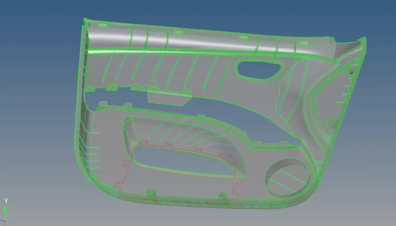
- The model has a lot of geometrical errors - incl. missing surfaces, deleted faces, free edges at undesirable places.
- Before performing mid surface or manually clearing for geometrical errors, the model is cleaned using autocleanup tool.
Mid-surface extraction
- After cleanup (defeaturing) the model is extracted for mid surface. However since the model still has geometrical errors i.e unclosed volume, the auto mid surface is still used to generated mid at those surfaces that are capable.
- The geometrical surface model can either be cleared and again mid surfaced automatically or can be extracted manually at one side of the face without geometrical surface optimization.
- The model extracted using auto mid method is shown below.
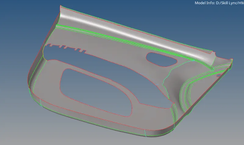
- While a few features havent been extracted, these features can be extracted manually.
- Since each component or feature in this model has different thickness, it is advisable to create individual component collectors for each and assign its respective thickness in the property card.
- The main component has a thickness of 2.8mm and the smaller features like ribs have a different thickness. Hence a seperate collector is useed for them
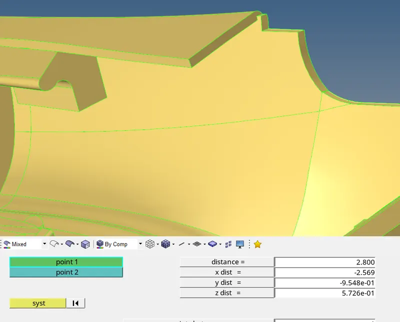
- Then fillets that fall within the radius of 1 - 6mm are identified and eliminated. This can be achieved from the following command: Defeature - surf fillet - find (1-6) - remove.
- Every rib feature that contains a fillet is removed and made into a rectangular shape (as shown below)
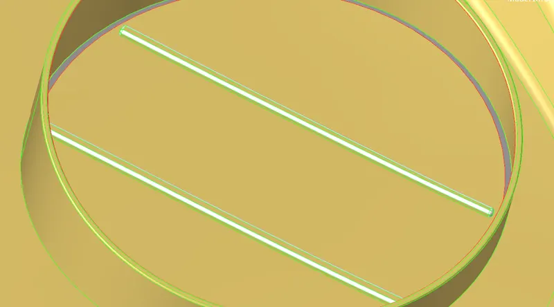
- To generate the mid for the above mentioned rib feature:
- Measure the distance between the two end points of the rectangular rib. If the end points are not aligned properly (i.e perpendicular) then the mid of the length can be defined by a point on both sides and measured.
- Using surf offset command one side of the rib is selected and offset towards the other side (half of end point distance)
- Before offset duplicate the selected surf/comp to a new or current comp collector.
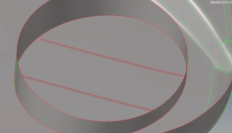
- Similarly other ribs are mesasured for their thickness and offset into a seperate component collector to which a new property id is assigned with its following thickness
- In the top part the series of arranged ribs are measure for their thickness which averages about to 5mm. These ribs are first defeatured as : Defeature - surf fillet - find (1-6) - remove.
- Then one face of each ribs is selected - duplicated to a new comp. (ribs) - and offset.
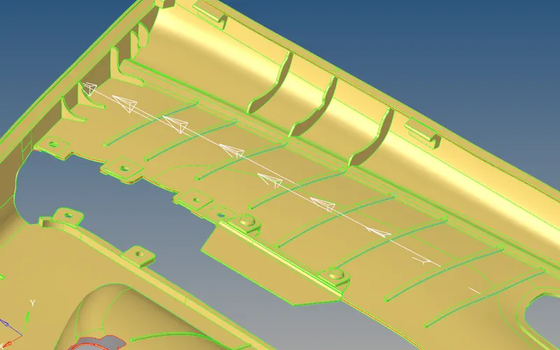
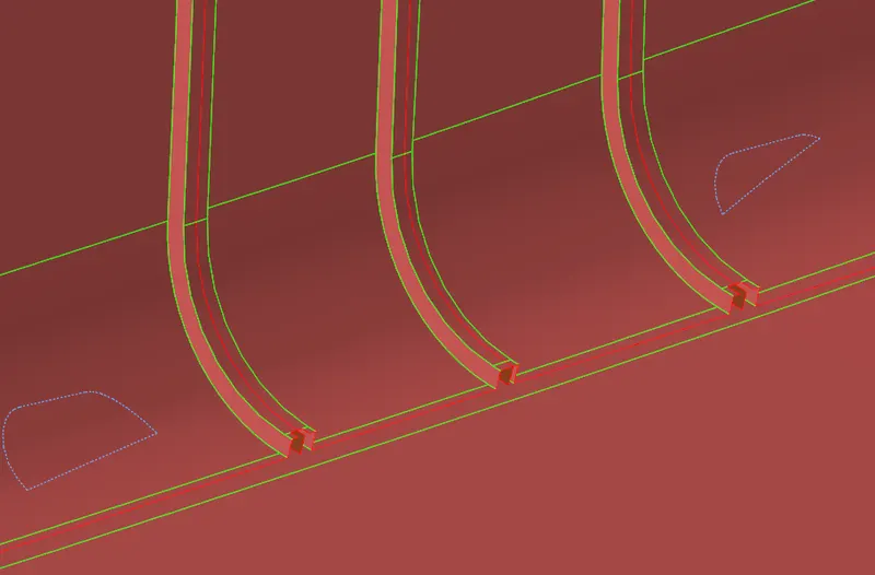
- In few cases, due to presence of mis alignment of due to geometrical lines, the defeature option may fail to capture fillets in ribs. To rectify this, the ribs are first toggled on the mis aligned lines and then defeatured (as shown below)
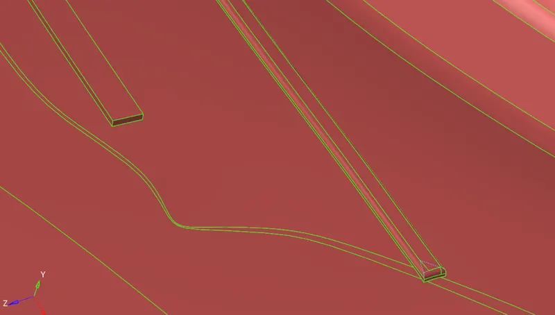
- Likewise, the two ribs shown in the above image are of different thickness (6.4 and 5 respectively). Hence for the first rib a new property card has to be defined and a new component while for the second rib the previous rib card pertaining to 5mm thickness can be assigned.
- Other small feature that extend or intersect can be cleared either using the extend or trim surface with surf option in the surface edit tab. It can also be achieved from the quick edit tab if possible (as shown below)
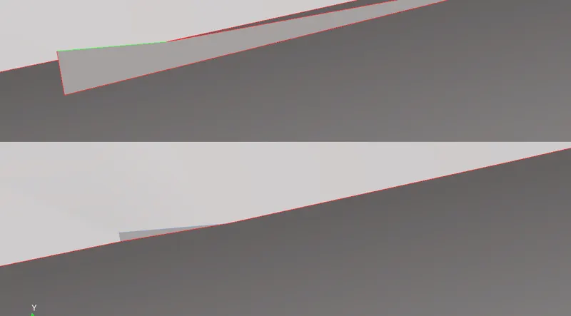
- Every rib has to be defeatured for smaller fillets and offset using surf edit. If defeature fails to stitch certain features together after removing the fillet, then the surf with the clear and perfect capture can be moved.
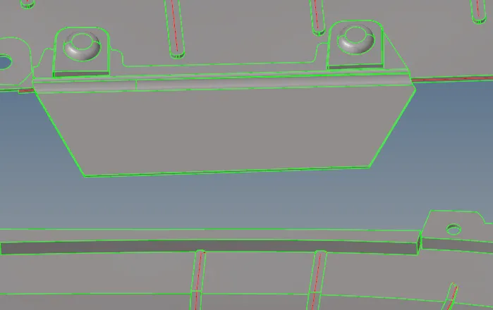
- The below component, is not extracted for mid surface since it doesn't have a proper attachment with the rest of the model
- Certain features in the model need not necessarily be modeled as it is. Features with a tapered edge or thickness can be modeled only as a flat surface with necessary holes that need to be capture is present.
- To capture such tapered edges on features:
- Extract the edge lines using: Lines - extract edge - select the surface - current (mid) component - extract
- Trim the mid surface with the line
- Delete the circular hole surface
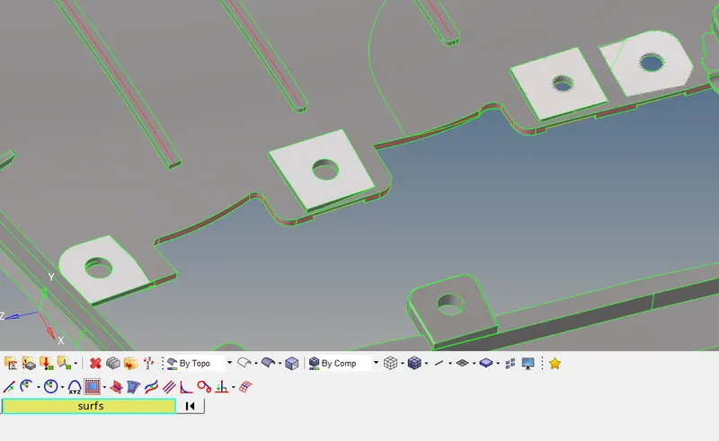
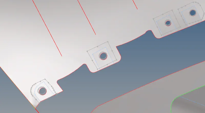
- Since the simulations are required to give approximate results, the ribs dont have to be accurately captured. Hence while extracting the mid, the ribs can be extended onto nearby surfaces using surf exit option.
- Cylindrical components dont really have to be modeled as a cylindrical shell feature. They can be modeled as shell plates which capture the width of the component (as shown below)
- To extract the mid of a cylindrical comp:
- Extract the edge lines of the component using lines - extract
- These lines capture the perimeter and outer edges of the feature
- Create a surface using two diagonal line extracts.
- After surface creation, delete the lines using delete command
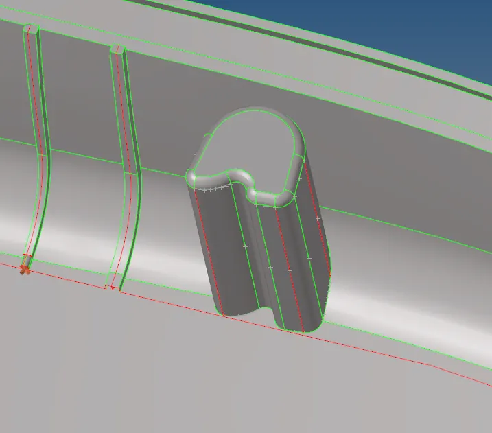
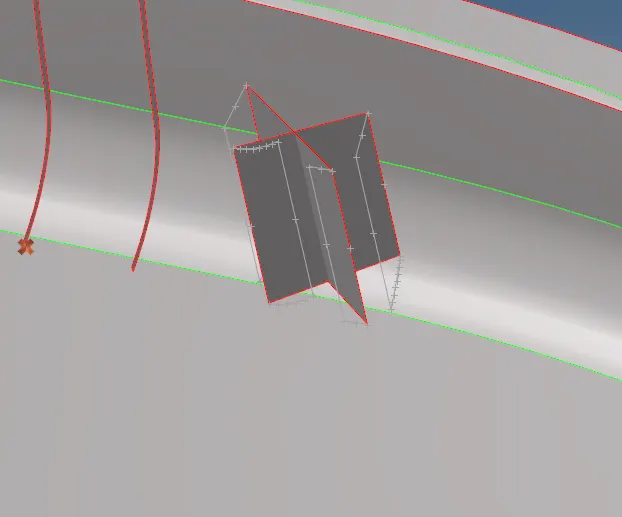
- In the end after extracting all the mid surface of large components or ribs, the ribs and other surfaces that dont have connectivity with its adjacent surface is are extended to make contact with it.
- Finally the generated manual mid of the entire model is shown below
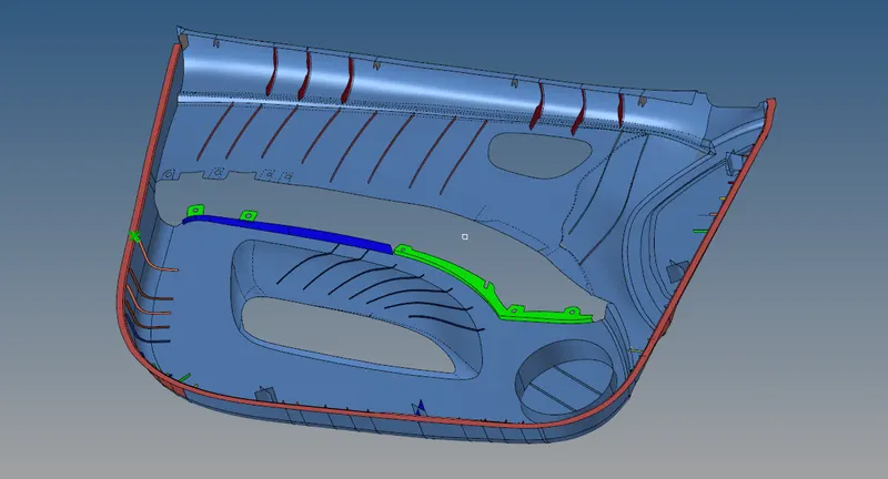
MESHING
- To mesh the component, first each ribs are meshed with quad elements and every hole is modeled with a washer first and then meshed.
- To create a washer: Quick edit - washer split - tolerance - select hole lines
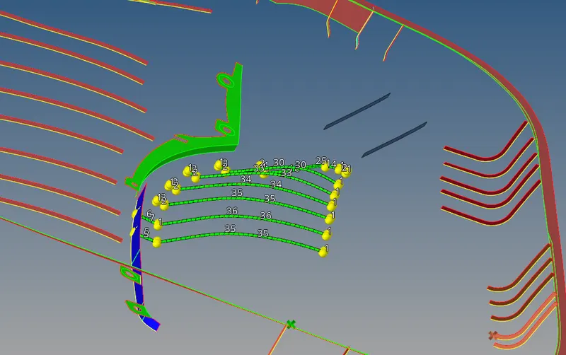
- While meshing ribs with quads, due to geometrical errors and alignment, to generate a smooth mesh flow with no trias the surface is split with elems in the middle. While this may clear the flow alignment however this would create small elems that would fail for aspect ratio or min length.
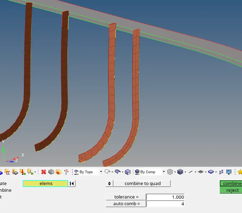
- Hence such small elems can be combined with the nearby quad so that they can clear the quality error. To combine elems: 2D - edit elems - combine to quad - select two elems - combine
- Finally the entire meshed component is shown below
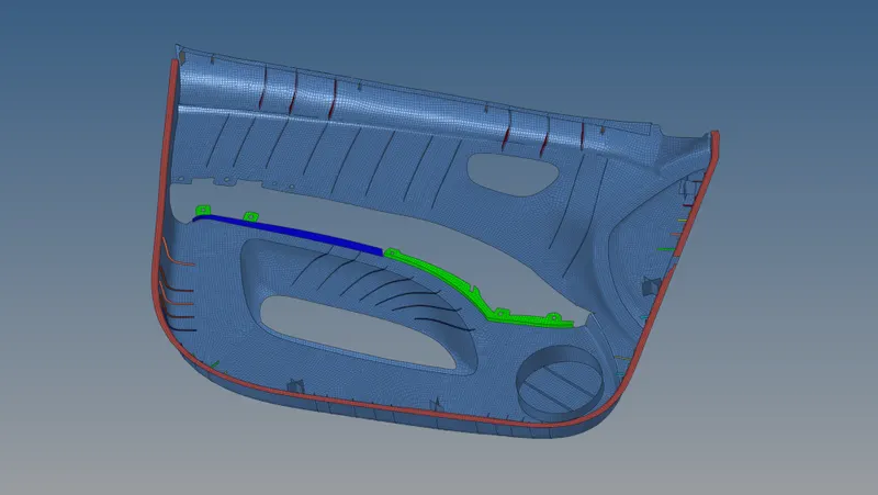
CONCLUSION
Hence the entire side door model has been extracted for mid surface and sucessfully the surface mesh elements were generated using Hypermesh. The property and material card have been assigned for each and this can be visualized by selecting the '2D Detailed element representation' (as shown below)