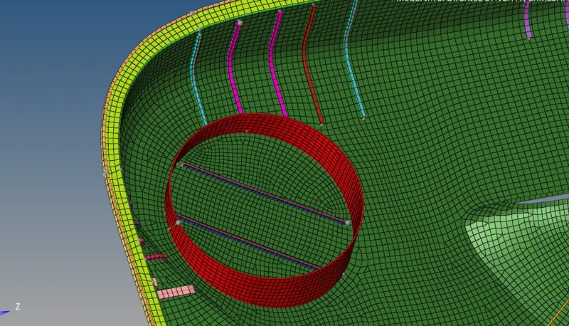
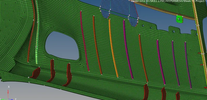
PREPROCRESSING ON A SIDE DOOR COMPONENT BY USING HYPERMESH
AIM :
To Performing a Preprocessing operation on which a given car side door plastic component, all should be done in Hypermesh software.
OBJECTIVES :
1) To Geometry Cleanup on a parent component.
2) To Generating the middle surface by using Parent components.
3) To Perform Geometry Cleanup on the extracted mid surface.
4) To Perform meshing operation on a extracted mid surface by using mixed elements with low trias concentration.
5) To Checking the element qualities as per given element criteria.
6) To Assigning the thickness on a middle surface in proper manner.
CAD MODEL :
Open a Hyperworks Software, set the User Profile which is "Optistruct" it means Optimization enabled structural Analysis. Click the "Import Solver Deck" Option for which importing the appropriate file, subsequently choose the "Import Model" option because given model has (hm) file and then followingly choose the appropriate file which we gonna perform preprocessing operation.
After importing the model, by default hypermesh set into the "Auto mode" from where "Geometry color mode" GUI option. It will looks like a below image.
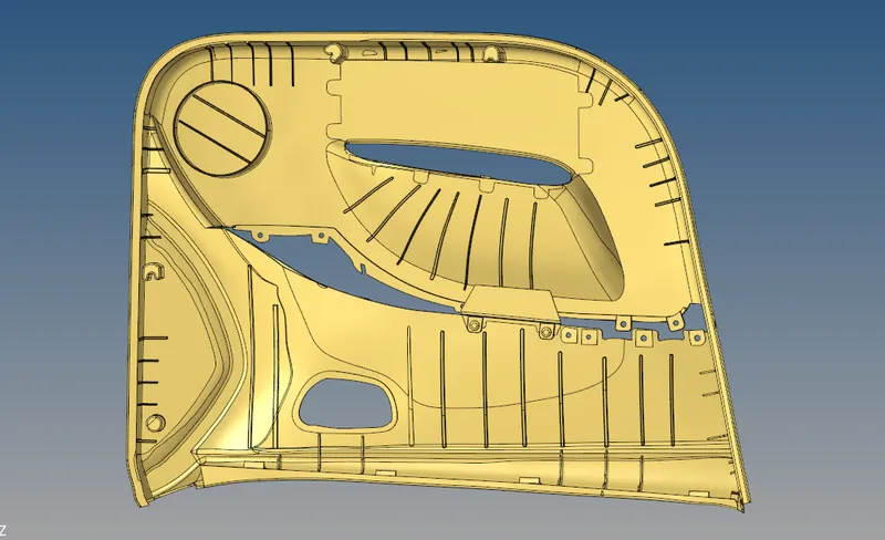
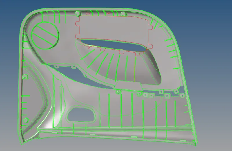
We have to manually changed into "By Topo" Mode instead of "Auto Mode". A "By Topo mode" which are helps us to visualize the topological Edges such as Free, Sharped, Supressed and then Non-Manifolds edges on a given component.
Make sure delete the solid part from the parent component, if solids are presented in the given component. In this component, completely have only surface.
After changed into "By Topo" mode, it will looks like as shown in the below image.
PROCEDURE FOR ACQUIRING THE OBJECTIVES :
i) Geometry Cleanup On a Parent component :
In this model, We have to manually geometry cleanup on a given side door component. It's clearly visible to our eyes, some big surfaces are missed. We have to create a appropriate surface atwhere cleanup has needed by using some given tools which are presented in the Hypermesh.
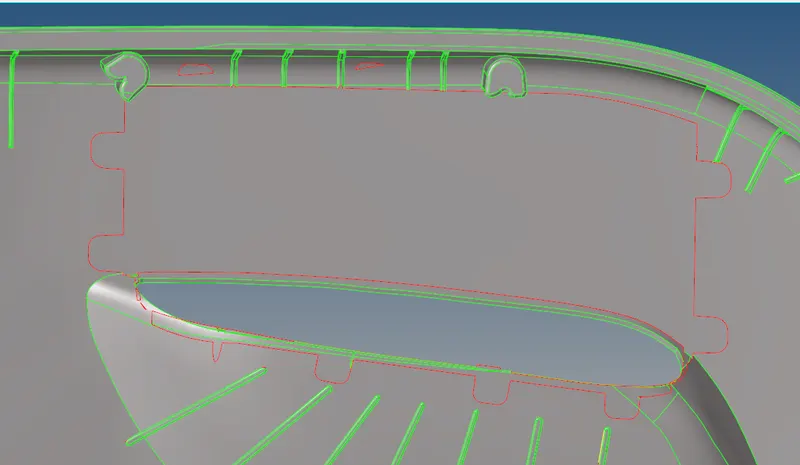
As we notice, we have create a another few small surface on a component atwhere surface had missed.
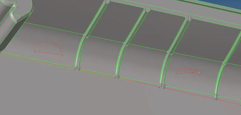
And also some topological edge error were found, look at the snap as shown in the below.
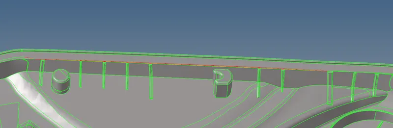
By Using "Toggle Option" to convert into Sharped edge with appropriated tolerance value. And another method, we manually add few point on both lines and followingly use "Replace Point" option for which converting into Sharped edge line. After cleanuping, a parent component corner will looks like as shown in the below figure.
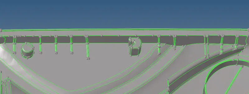
By using "filler" option or else "Ruled" option to filling the small gaps in the component and then supressing that sharped edge line by using toggle option.
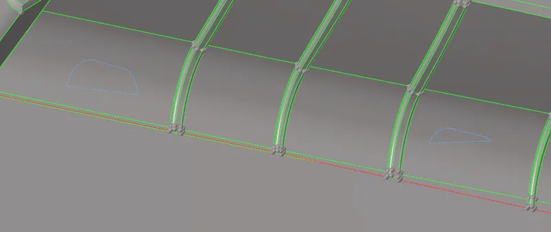
After Completion of geometry cleanup on a given parent component, it will looks like as shown in the below image.
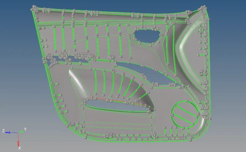
ii) Generating a middle surface :
Basically, a mid surface which means surface created betweeen two surface, it will hepls us to minimize the calculating time, storage space and then gives better results as well. In this case, we gonna extract manual middle surface by using "Offset" Option.
Method 1 :
Before gonna perform extract the mid surface, we have measure the appropriate thickness between the surfaces. It's very crucial to measure the thickness between two surfaces which are in the middle part.
Inorder to measure the thickness between them, we have to create the nodes on a top surface and then project into bottom surface by using "the Surface Project" Option.
Go to the " Distance" panel under which geometry main menu panel or else directly press the "F4" button from the keyboard. Choose the "two nodes" option, select the one node from outer surface with followingly select the corresponding node from the inner surface as well. A Hypermesh automaticallly detect the distance between two nodes depends on selection of nodes.
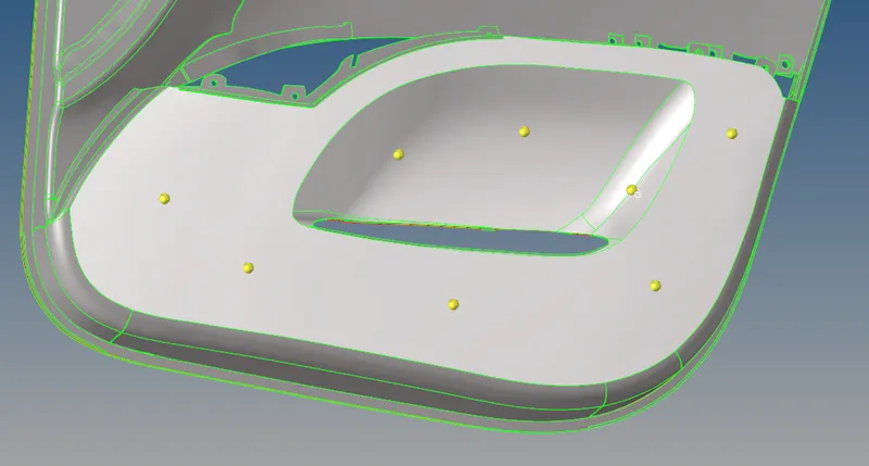
After selection is done, we gonna generate middle surface by using Offset" option under which "Surface Edit" panel.
In this component, a thickness is varying at different different regions. First of all, take a one part from the component which thickness has same throughout the particular part.
As we know, middle surface is created between exactly at middle of the portion. So, we put the offset distance which is half a thickness of parent component thickness and then choose the respective surfaces which are same thickness as we keep in the offset distance.
Make sure create a new collector for which organizing the generated middle surface and after which we have to create a duplicate from the selected surfaces before going to offset.
Make sure check the Vector direction, all we need is middle surface has been generated between the respective selected two surfaces.
After Clicking the offset option, it will automatically creating the surface between them.
Method 2:
In this method mostly perferable to ribs parts, inorder to create a middle line. First of all, we gonna "Lines" panel under which " Geometry" main menu panel and then followingly to select the "Midline" option.
Select the "Line list 1" with choose the set of lines, then moving on "Line list 2" with choose another set of lines and then finally click to create a mid line between those where selected in the line list.
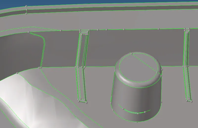
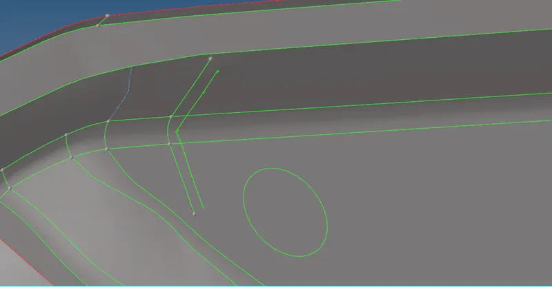
After creating the mid line, we gonna trim the surface which is correspond to ribs. First of all, we have to go "Surface Edit" option, followingly choose the "Trim with lines" option.
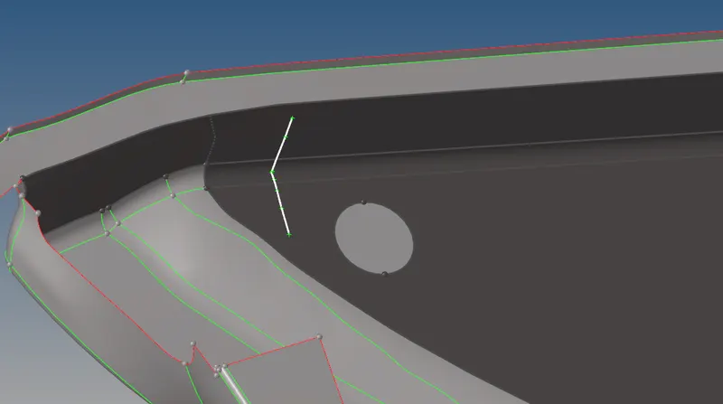
From this option, choose the respective surface and then choose the respective lines, afterthat click to trim the surface. It will trim the surface at where exactly perpendicular to the selected surface.
Black color surface has represents by selected surface and white color line has represents by selected line which are shown in the below snap.
After trimming operation had done. It will showing like below image.
Go to the "Surface" option under the geometry main menu option, from there choose the "Ruled" option. Select the any one of the line for which line list 1 and then select the remaining one line for which line list 2 with followingly click to create the surface between the two lines.
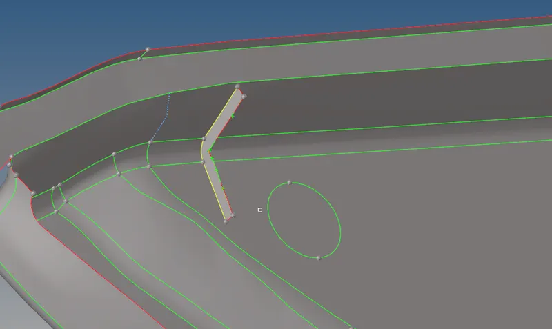
After creating the surface, a mid line is unwanted thing. So, we manually delete that particular line by using delete option.
Similarly, we have to do all the remaining ribs except some ribs.
I) Creating a Mid line for bigger cyclinder :
As we notice the bigger cylinder, it has some slightly inclined from top thickness to bottom thickness. In this case, we have to consider the both thickness for which extract proper mid surface on itself.
i) Creating a midlines :
We have to manually create a mid lines on which both top & bottom by using "Mid line" option from where under the "Surface" option.
After creating the mid lines, it will looks like as shown in the below image.
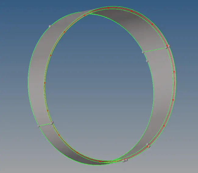
It has clearly visible to our eyes, some inclination are presented due to thickness were varying between top & bottom cross section.
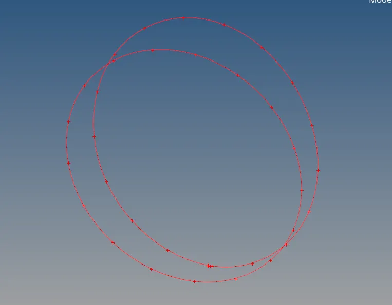
ii) Creating the surface between the mid line :
By using "Ruled" option to create a surface between two mid lines. After creating the surface, it wiil looks like as shown in the below image.
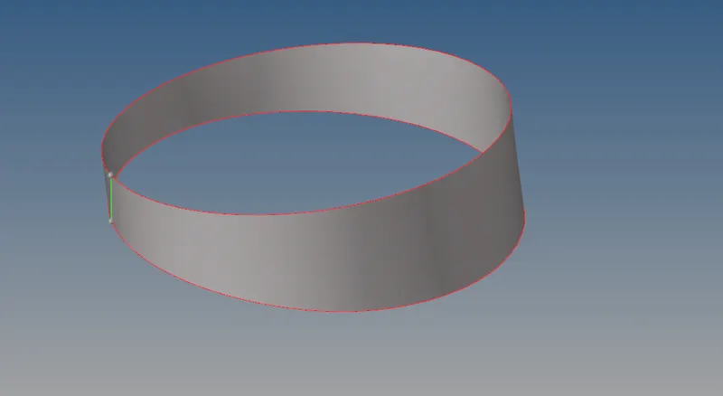
Method 3
In this case, If we use "Mid line" option to which create the mid surface between two surfaces, actually it will take some more time compared offset method.
Inorder to create a middle surface by using offset option. First of all, we need to measure the thickness of the particular ribs and then put the offset distance value which is half a thickness of particular parent rib thickness.
Selected ribs thickness are same which is 2mm as shown in the below image. Make sure create a duplicate surfaces before gonna perform offsetting.
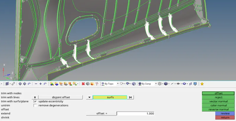
After Offsetting rather generating the middle surface at which particular ribs. After that, we have to extending rib surface upto target surface by using "Extend" option under which "Surface Edit" option.
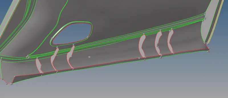
Complete Extracted Middle Surface :
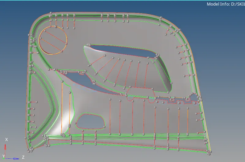
After Completion of middle surface generation to entire component, it will looks like as shown in the below image.
iii) Geometry Cleanup on a middle surface :
Actually, Created middle surfaces are proper throughout the component. In this created middle surface, there's no need of geometry cleanup, but we have to consider element criteria range. So, we need to suppress some lines or else create a new lines for which capturing the proper mesh flow with affecting the element quality.
iv) Creating the meshing on a middle surface :
To discritization of a entire component into infintesimal control volume, that frame work is called meshing. This process is called discritization.
Go to "Auto Mesh" option under the "2D" main menu panel or else directly press the "F12" button from the keyboard.
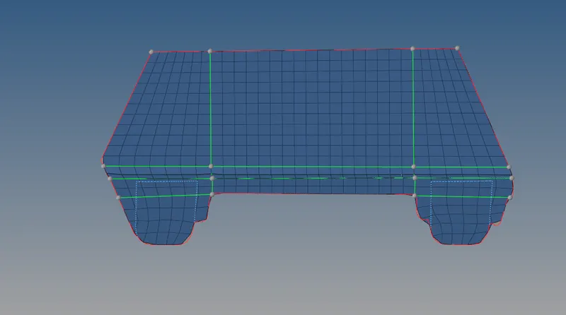
By using "Auto Mesh" option to which create a elements on a surface by using element size is 4mm and element type is "Mixed". If the created elements are bad, we have to change the elements mode instead of surface mode for which remeshing the elements again and again whenever elements gets proper.
Similarly create a mesh elements on a entire component surface itself.
For creating the elements, We should concerned the meshing conditions such as "Low trias concentration", "Proper mesh flow with same element type", "Remove Opposite trias", " Avoid trias are failing along the feature line", "Proper feature capture" and then "connectivity between the elements".
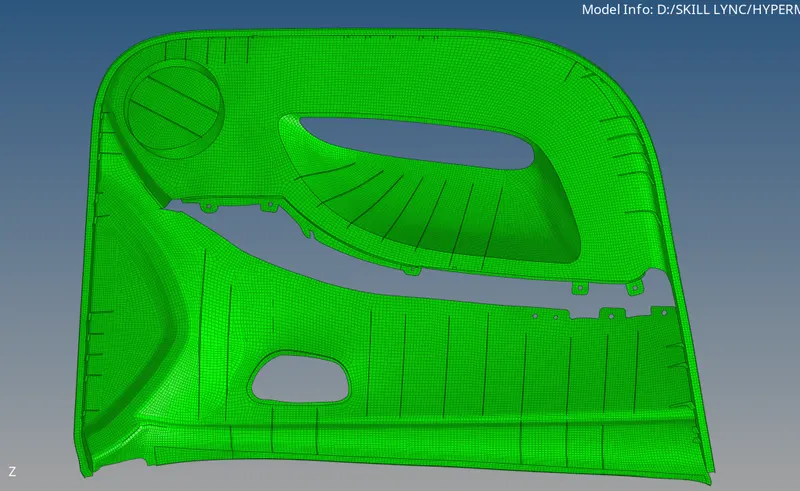
After completion of meshing operation, a meshed component as shown in the below image.
v) Checking element qualities :
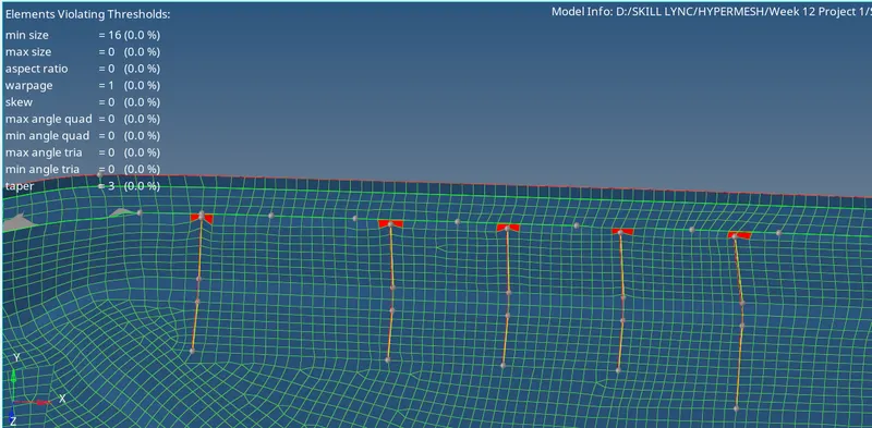
All elements are satisfied as per given in the element parameters except some few elements failing due to feature line at where folded portion.
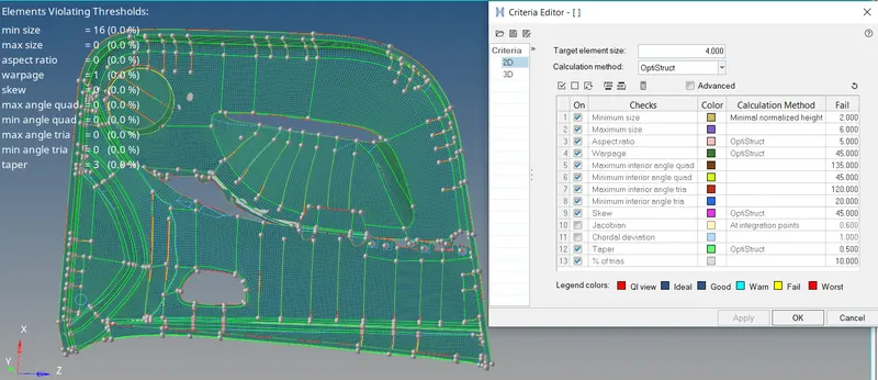
Some few minimum element size has failing due to presents of ribs atwhere folded portion. In the case, Particular element failing has acceptable.
vi) Assigning the thickness :
In this case, a parent component thickness is varying in different different region. Inorder to assigning the thickness, we have to create a new collector followingly organize the corresponding elements and surfaces.
For that particular component, we have to create the new property with provided appropriate thickness value.
Similarly, we have to do each and every varying thickness parts.
In this component, we have 26 number of components, 23 Number of Property cards and created a one material card which named as plastic.
After creating the property card & material card, we have to assigning the appropriate property & material card to the corresponding component.
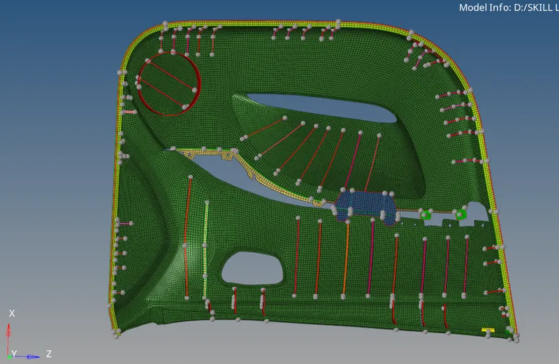
Inorder to visualization of assigned thickness, we have to change into "2D Detailed element representation" instead of "2D Traditional element representation".
After Assigning the thickness, it looks like as shown in the below image.
CONCLUSION :
Successfully completion of preprocessing operation on a given side door component like geometry cleanup on a parent component, Extracting the middle surface from parent component, Meshing on a middle surface as per given element criteria, Quality checking and then assigning the thickness as per given parent component thickness.