Week 12- Final project
Objectives:
- Create thickened part using the master section for reference
- Create the mounting features as per design guidelines in the industry and with master sections
- Apply material details :
- Draft analysis & Tooling analysis
- Creation of parting lines and check tooling feasibility
Procedure:
Given Class A Surfaces:
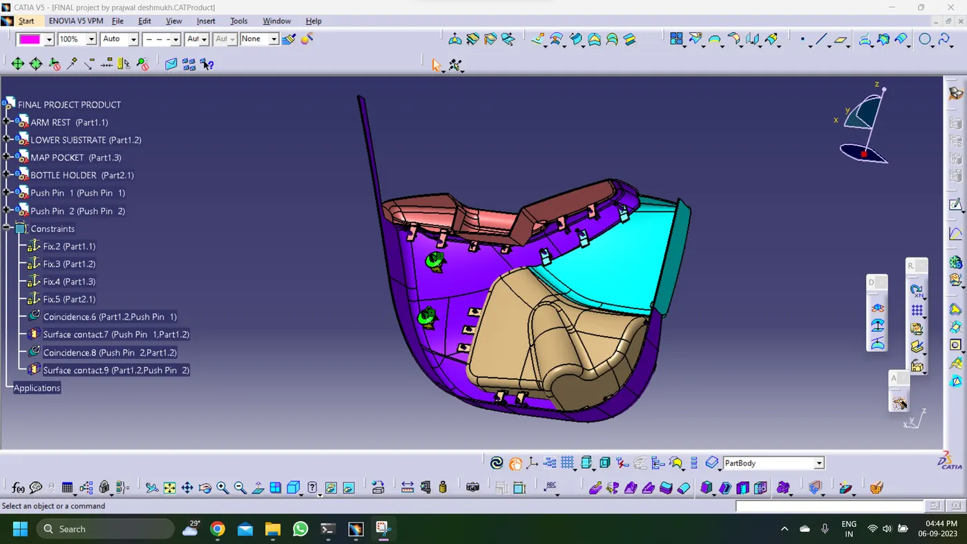
The Class A assembly:
For each part:
- Class A surface was analyzed first.
- Some corrections were made in class A surface first.
- Tooling Axis was created.
- Draft analysis was performed.
- Then Class B surface was made by offsetting the corrected Class A surface.
- Class C surface was made by using the edges of the Class A surface. Then Class A and C were joined together.
- Now this A+C and B surface were trimmed together. This results in a closed surface.
- Then this final trim was thickened in Part Workbench.
Heat Stakes:
On the lower substrate :
- Two concentric holes were made and extruded along Y-axis up to 23 mm.
- Draft of 0.5 was provided to the inside and outside faces.
- Two intersecting lines were created and extruded up 10mm. This is the rib of the heat stake.
- Now the rib was joined to the main body using the union trim command.
- Draft of 0.5 degrees was provided to the walls of the ribs.
- Fillet of 0.25 was provided to all the edges.
Locators:
- A 15x15 cross was extruded up to 25 mm.
- Draft angle of 0.5 degrees was given.
- The top edges were given a chamfer length of 3 mm and 45 degrees angle.
- Fillet of 0.25 was provided to all the edges.
The 4-way locator is clearing the 0.5-degree draft.
Now, copies of the heat stake and 4-way locator were created and these copies were translated to different locations as required.
Then these copies were then added to the lower substrate body.
Flanges:
- Flanges were created according to the given master section.
- For the flanges, two sketches were created. One is attached to the C section of the body and the other is parallel to the base surface. The bottom tip of Sketch 1 was coincided with the intersection of a plane and the surface of the body. In this way, we get a line whose one end lies on the edge of the C surface.
- Pink line- sketch 1, purple line- the intersection of the body and the plane.
- This plane was created with reference to the center of the base circle of the heat stake present, and parallel to yz plane.
- Sketch 2 was created according to the master section.
- Sketch 1 was wept along the edge of the C Surface and Sketch 2 was extruded along the line joining the center of two heat stakes.
- Then these flanges were thickened to 2.5 mm in the above direction.
- A hole is created in the flange by extracting the surface of the heat stake and offsetting to a certain value.
- the side walls and the hole face were drafted by and angle of 0.5 degrees
- Fillet radius of 5 mm was given to the front facing vertical edges and 0.5 mm fillet was provided to the rest of the edges.
- The B surface of the lower substrate was extracted and then a point and a plane was created.
- This sketch was swept up to 50 mm above and 3 mm below with an angle of 1.5 degrees.
- Then the top was closed using the multi-sections surface command and then joined with the swept surface
- Then this was thickened to 2.5 mm
- A line was created on the plane parallel to it and then extruded.
- This was then offset to 5 mm and then trimmed with the main surface, this was then offset to 1 mm toward the solid body.
- This was then trimmed with the main surface and we then get a surface like this.
- This was then split with the solid body.
- Appropriate fillets were given to the edges.
- Then draft of 0.5 degrees was provided to the inner walls with respect to the side core tooling axis.
- Then rest of the features were added as per the push pin dimensions
Conclusion:
- Thickened part using the master section for reference was created.
- The mounting features such as 4-way locators, heat stakes, and flanges as per design guidelines were created. In the bottle holder, the flanges are intersecting with the part body despite being created using the design rules, and hence changes in the design of Class A surface are needed.
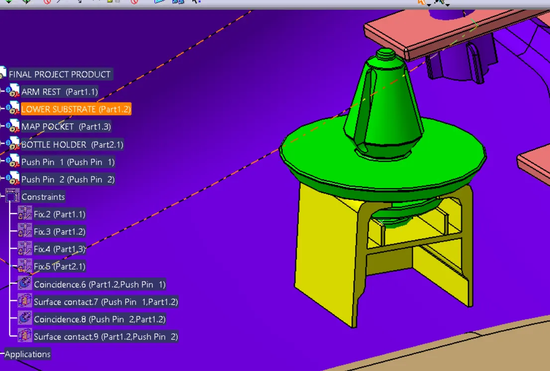
- Dog houses and the push pins were assembled.
- Draft analysis was performed.
- Plastic material was added.