Week 12- Final project
Aim: In this project we create the door trim panel Components that is (Lower substract,Arm rest, Bottle holder, map pocket) with the necessary input surfaces provided and generating the necessary B side features ( heat stakes, 4 way locators, Dog houses, push clips, Ribs, screw bosses etc) thereby assemble the individual components of the door trim by providing proper constraints there by performing the proper draft analysis using catia V5 software
Objective :
The main objective is to create the individual components of the door trim with input class A surface provided and generate the class B and class C surface and produce the solid surface body out of it and perform the proper draft analysis with required draft angle of 3 degrees for the body and continue the procedure for the remaining components .Then start creating the B side features of the components by following the reference of the master sections provided and perform the draft analysis with an input draft angle of .5 degrees and assemble the components to for the final door trim panel on the assembly workbench by providing necessary constraints using catia V 5 software
Procedure followed for the creation of the components:
- Analyse the input surface provided
- Class A surface as input surface
- Tooling axis creation
- Draft analysis of class A surface
- Class B surface creation
- Class C surface creation
- Solid surface body generation
- Draft analysis of the solid body
- creating the B side features
- Draft analysis of the solid body along with the B side features .
Class A surface:
Class A surface is an asthetic surface which is visible for the customer in the component
Class B surface:
Class B surface is an engineering surface where the B side features of the components like heat stakes, screw bosses, Ribs, doghouses are situated
Class C surface:
Class c surface lies as an intermediate surface between the class A and the class B surface thet means it generally accommodate the thickness of the whole plastic component
The input provided for the design is
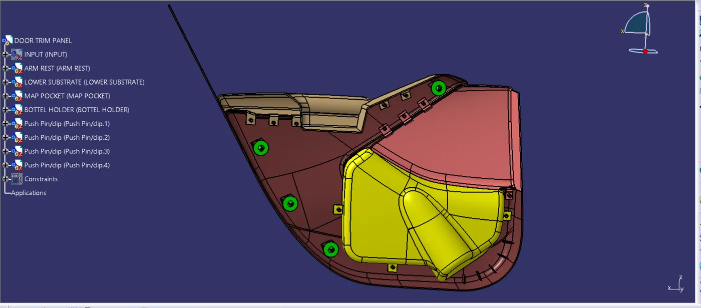
1.Arm Rest:
Re-creation of Class A Surface using with given input:
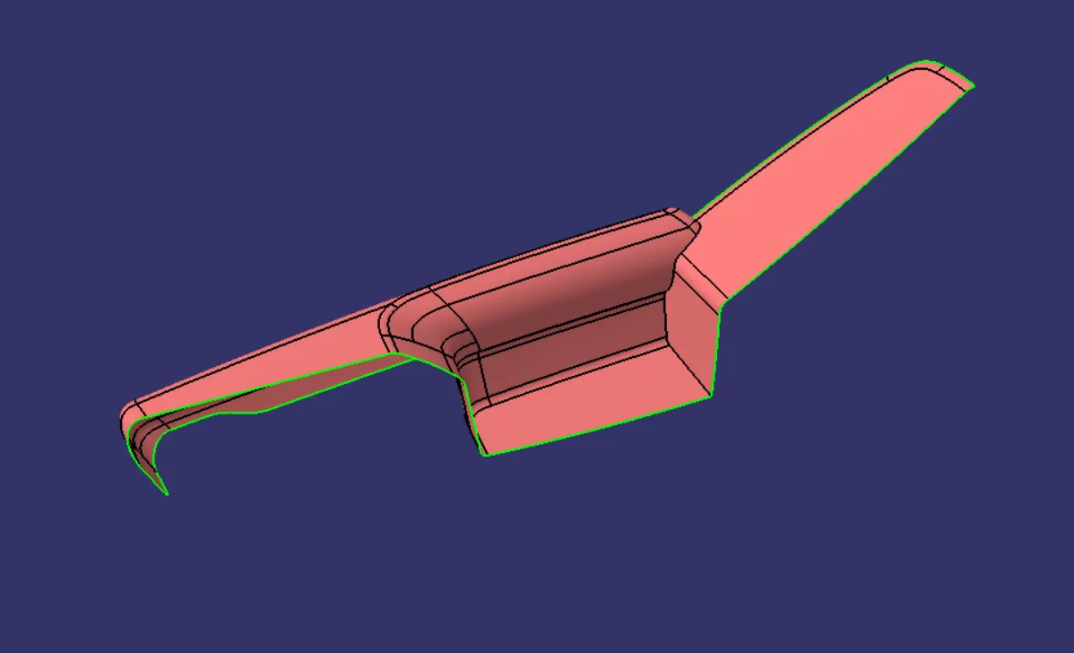
Class A Draft Analysis-
Tooling Axis And SideCore Axis:
- Creation of Class B Surface -
Class B surface is created by offseting class A surafce by 2.5 mm as per the mastersection. After offseting some area not get offseted , there patches formed. This patches are closed by surface creation features such as fill , multisection , blend etc.
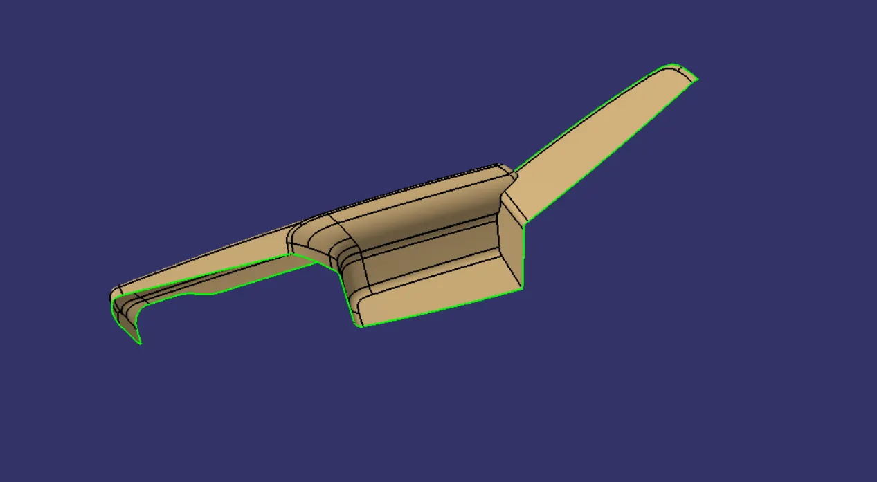
- Creation of Class C surface -
C surface is the connecting surface of Class A and Class B surface. By using Sweep we created the Class C surface. For that first we have to extract Class A boundary and then with draft direction at angle 3 degree we have sweep the class A extracted boundary. And we get the Class - C surface.
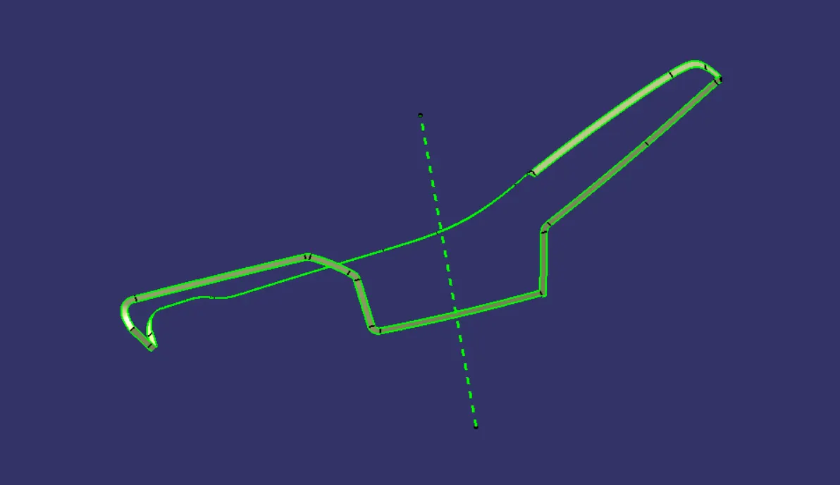
- Creation of Closed Body of Arm Rest - By trimming join of Class A ,C with Class B surface we get close body.
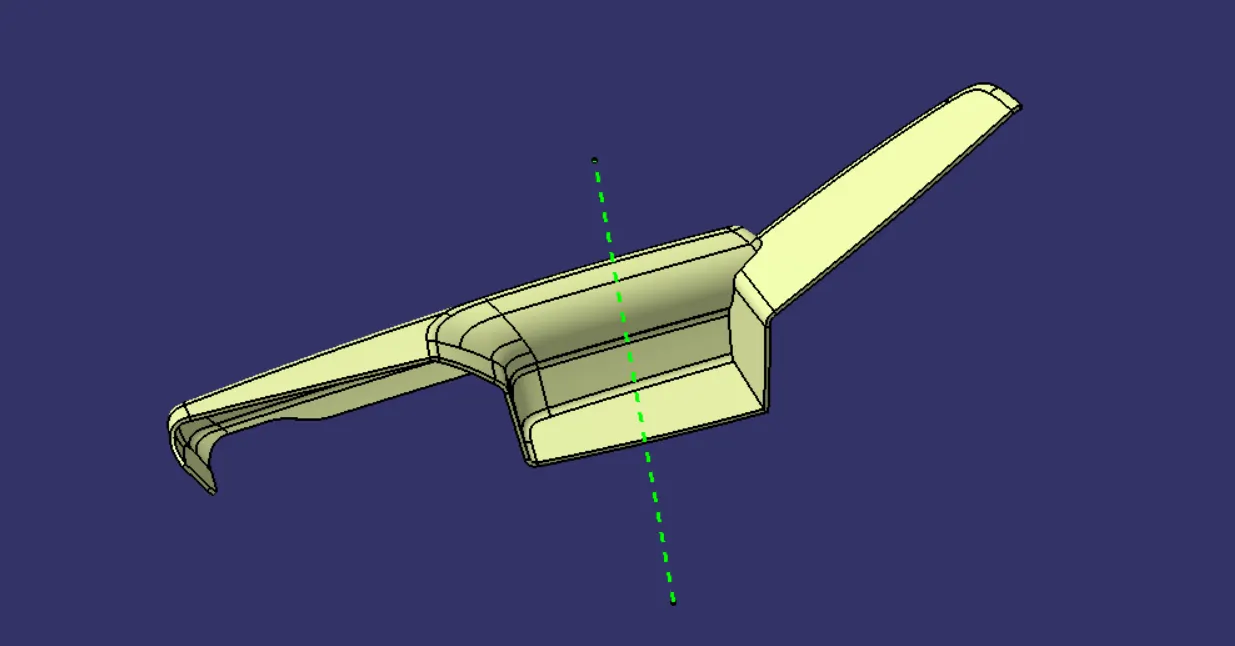
- Creation of Flanges on Arm Rest -
From mastersection we get the idea of flanges . I have created flanges on Arm Rest by considering counterpart (Lower Substrate) position.
- Draft Analysis on Soild Body of Arm Rest -
DRAFT : The draft is something that allows the componenet to release or eject from the mold properly. The draft is required on all parts in the direction of mold movement in order to allow parts to release properly. Most parts or applications require a minimum of 1/2 to 1 degree, however , 3 degrees is widely accepted as the norm.
The draft is given in the direction of tooling direction or core cavity opening.
If we don't give the draft to the component it strick to the mold and friction alos act so we get the damage in our part so to overcome this we give some draft angle to overcome this problem.
As mentioned above we have two tooling axis for Arm rest.
2. Lower Substrate:
Class A Surface:
Tooling Axis:
- Creation of Class B
Class B created by offseting class A by 2.5 mm.
- Creation of Class C
- Creation of Solid Body
- Creration of Heat stake
HEAT STAKES -
- Heat stakes are used in thermoplastics to assemble two parts together by locally heating and cooling the plastic material and allowing it to reform itself and act as a joint for the two materials.
- We have placed 9 heat stakes in the model based on the reference points created by estimation.
- One of the important factor to be considered while designing the heat skates is the height of the heat skates. It should always be less than the height of the locators.
- Creation of Locators
LOCATORS -
- The main purpose of locators is to facilitate proper locking of two components together while assembling and arrest the maximum degrees of freedom possible.
- These locators are similar to guide pins provided in mould.
- The two types of locators used are two way locator and four way locator.
- We have positioned three 4 way locators in our model which meet the rib design criteria.
- Creation of Dog House
DOG HOUSE -
- The two main purposes of a dog house are to avoid sink marks and to house various other engineering features like screw boss, locators, push clips etc.
- In this case, the dog house is designed to house the push clips and the 4 way locator. The dog house designed for the push clip features a slot on the top face to accommodate the push clip
- The dog house should follow certain design rules which are stated below
- Doghouse wall thickness at the intersection of the part wall (C) should be 40% or less than the main wall stock (T).
- The height of ( B ) should be between 3.0 – 6.0 mm
- Outer surface of dog house must have a draft angle of 3 degrees
- Inner surface of dog house must have a draft angle of 0.5 degrees
Draft Analysis on Dog House -
- Class A Surface
- Check quality of Class A
- Improved Class A surface
- Creation of Class B
- Creation of Class C
For creating class C surface we have to use sweep feature of surface creation.
- Solid Body of Bottle holder -
- Class A Surface -
- Check Given Class A Surafce for improvement
- Draft Analysis on Class A -
- Creation of Class B
Class B surface is created by offseting class A surafce by 2.5 mm as per the mastersection. After offseting some area not get offseted , there patches formed. This patches are closed by surface creation features such as fill , multisection , blend etc.
Final Assembly -
For final assembly of door trim panel we have to constarin all parts together.
Following image shows the assembly of push pin with dog house.
CONCLUSION :-
From this project I have leraned how to create CAD model for plastics parts by considering design rule. By doing this project on Catia V5 , I get very well familiar with part workbench ,surface workbench , Assembly workbench. Also I get confidence in handling different features of all workbenches. Along with this , I get idea of how to design a part by considering manufacturing and assembly aspect.