Week 12- Final project
Final project
Objectives:
The door trim panel, which includes the Map pocket upper lower, Lower substrate, and Door Armrest, serves as the input for the creation of tooling direction and performing draft analysis on the class A surface.
- Creation of a solid body and surfaces of classes B and C from a nearby surface.
- Ceating attachment features, including flanges and heat stakes, in accordance with the master section.
- The engineering creation includes heat stakes, ribs, doghouses, and four-way, two-way locators using these design principles.
- Create a dividing line after doing draught analysis on the last portion.
- Put every component together and add the push pines.
Given master file:
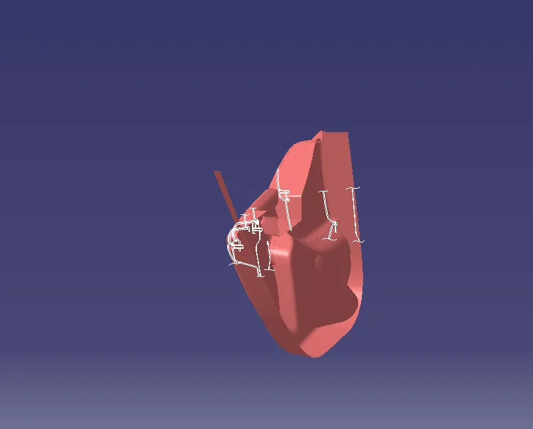
The entire visible plastic surfaces you see inside the car Dash board or ip, door panels, etc. are A surfaces. even the visible surface of bumper, fender, mirror housing, etc .Class A surface is a asthetic part of the part which is supposed to be in visual side of a part, which is going visible to the occupant or the viwer. class a side dose not have any engineering features and inpefection.
Class B surface
Class B surface is created according to the class a surface it backside of any part which have all the mounting features or say engineering features like heat stakes, screw bosses , doghouse, and in is not visible to viwer.
Class C surface
Class C surface is the surfcae which connects the class a and class b surface which have some imperfections and flashes this surface is not visible.
Design for controlling cost:
A fantastic technique to reduce mould costs is to design a part that can be moulded using a "straight pull" or "up & down" action. When the A side and B side of the mould split from one another, a straight pull mould is created so that there is no plastic to obstruct the metal's journey in the direction of the draw. This route obstruction is caused by undercuts on the component and calls for a mould action (cams, core pulls, etc.). The price (and total size) of a mould can be significantly influenced by what happens in the mould.
Draft work:
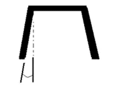
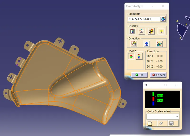
To correctly release or expel pieces from the mould, draught is necessary on all portions in the direction of mould movement. The part's draught is the angle at which it is tapered to enable release. The portion tends to desire to shrink to the mold's core side as it cools. Draught addition aids in portion release. The majority of components or applications need for a minimum of 1/2 to 1 degree, while 11/2 to 2 degrees is often regarded as the standard.
Bosses aid I assembly mounting:
Bosses can be added to the part design for assembly, locating, or mounting of a part. Improper placement of a boss leads to uneven wall thickness and can have a negative impact on the aesthetics, shrinking, or strength of a part.
Engineering features:
- Rib
- Screw boss
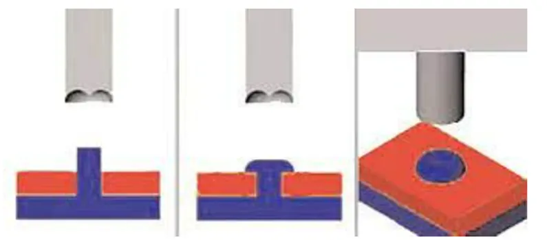
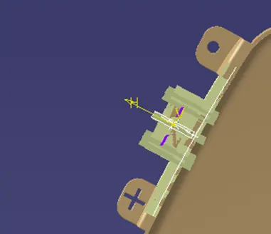
- Heat stake
- Doghose
- Locators
Rib:
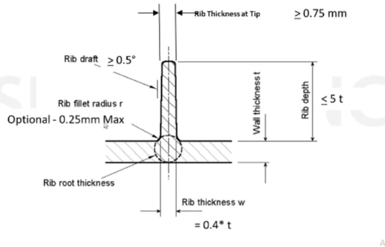
A part's bending rigidity is increased by ribs. To enhance the bending stiffness without ribs, the thickness must be raised. The bending stiffness is increased by adding ribs since doing so increases the moment of inertia. E (Young's Modulus) x I (Moment of Inertia) equals the bending stiffness. To keep sinking to a minimal, the rib thickness should be smaller than the wall thickness. The thickness varies between 40 and 60% of the thickness of the material. Additionally, the corners of the base should have substantial radiusing where the rib attaches. They are utilised to support these walls and bosses by running perpendicular to these structures. They are thinner than major walls. To prevent sink marks, warping, and cavities, large wall portions are frequently replaced with ribs.
Screw boss:
Bosses are used for the purpose of registration of mating parts or for attaching fasteners such as screws or accepting threaded inserts (molded-in, press-fitted, ultrasonically or thermally inserted).
The wall thicknesses should be less than 60 % of nominal wall to minimize sinking. However, if the boss is not in a visible area, then the wall thickness can be increased to allow for increased stresses imposed by self-tapping screws. screw boss its a engineering feature which have thread in so the screw can get insrted and hold its place tightly so the two part remain assebled. screw boss used to asemble two component with the help of screw.
Heat stakes:
Dog house:
Wall thickness = 0.70 x Thickness of the plastic material
Fillet on the inner side = 0.25 x Thickness of the plastic material
Fillet on the outer side = 1.25 x Thickness of the plastic material
Fillet on the coring edges = 0.25 x Thickness of the plastic material
Coring thickness = 0.40 x Thickness of the plastic material
Draft angle 2deg to 3deg
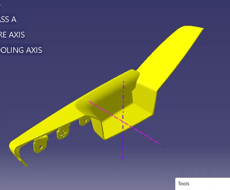
Tooling axis:
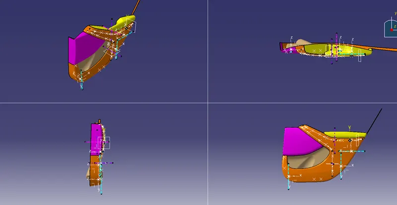
Tooling axis is a direction of mould opening and closing, in this part we used Y component as a Tooling direction for 3 part except the door arm rest because in this input is of the door arm rest is complex part it is not manufectured in one direction and we have to add to meany side core direction which will make the mould more costly. so we have to just inform the class a designer all the things.
the assembly in going to be in Y direction and it will make easy to create the enginnering features design
arm rest:
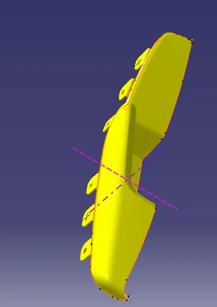
Tooling axis:
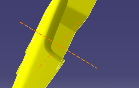
Class a+c:
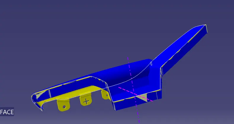
Final trim:
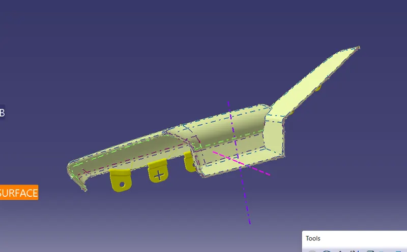
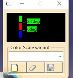
Draft analysis:
Final part:
Bootle holder:
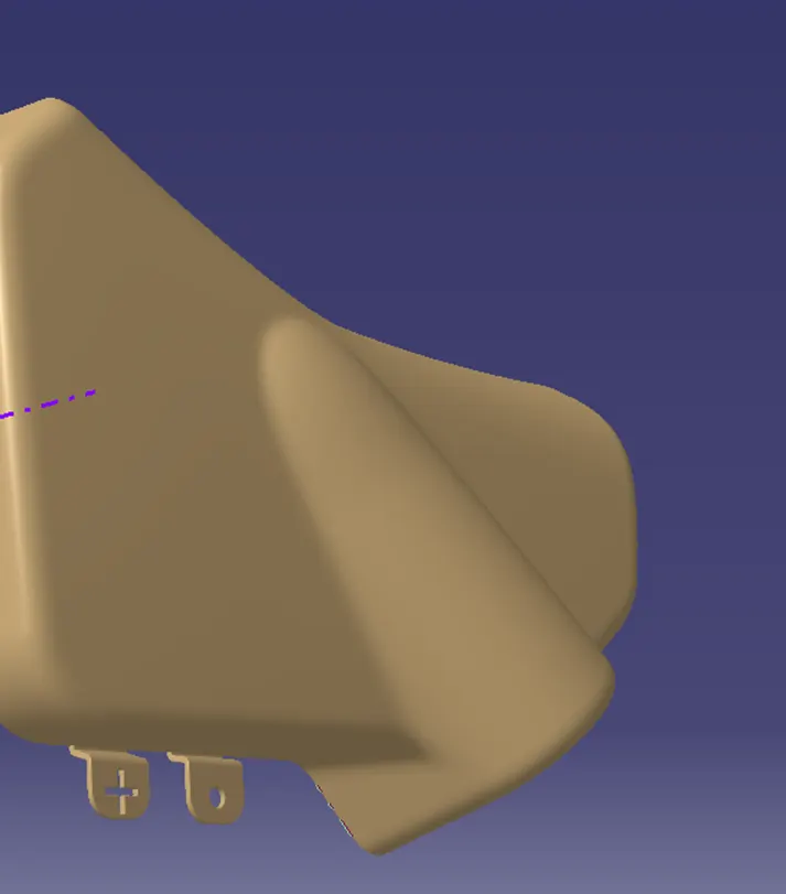
Class a :
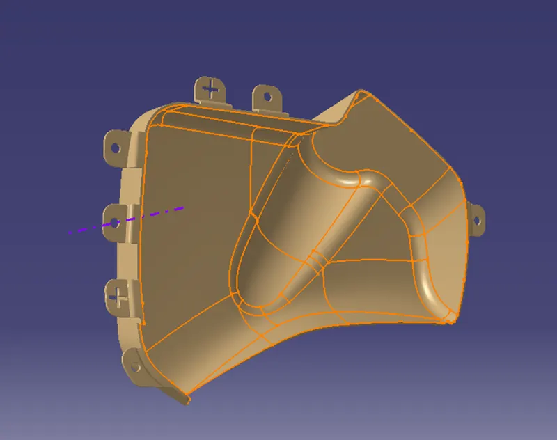
Class c:
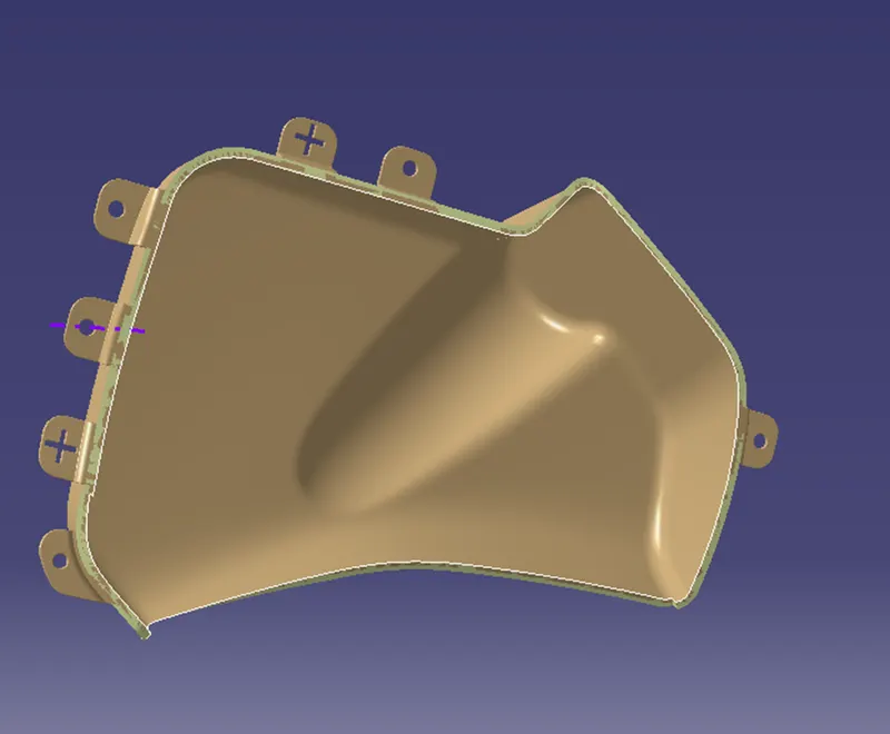
Class a+c:
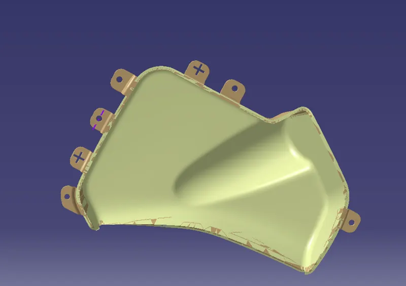
Flange:
Draft analysis:
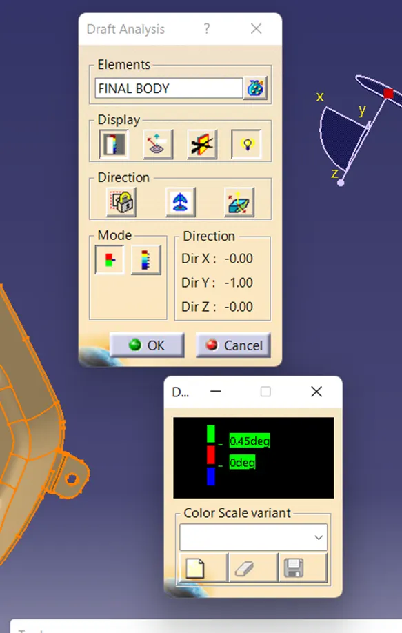
Map pocket &tooling axis:

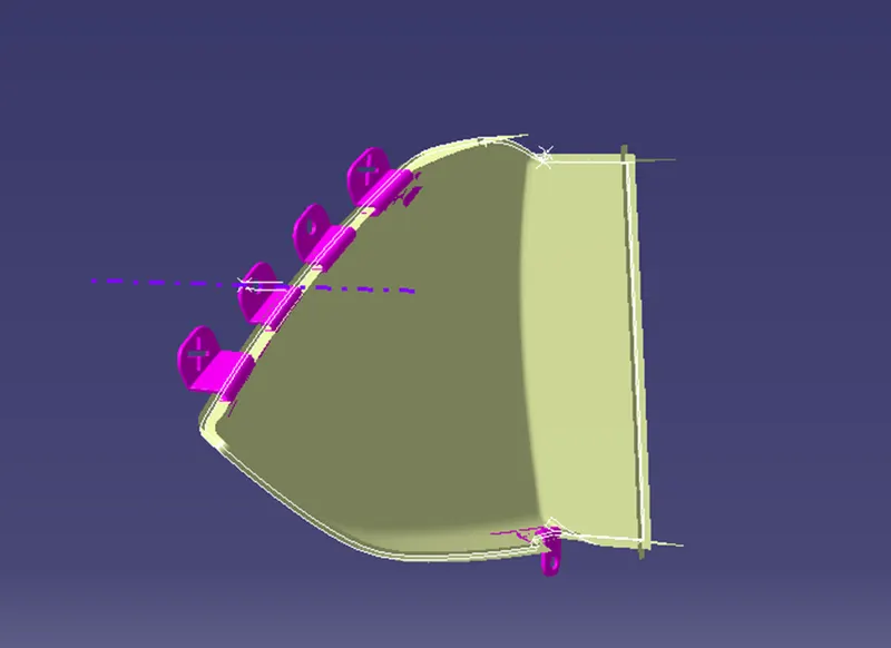
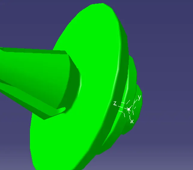
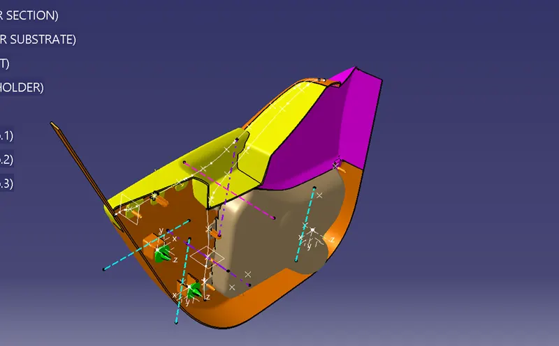
Assembly of project:
This is the stage where every thing is going to assembled
References:
Skill lync
Google & wiki