Week 11 - Project - A pillar Design with Master Section
A PILLAR DESIGN WITH MASTER SECTON
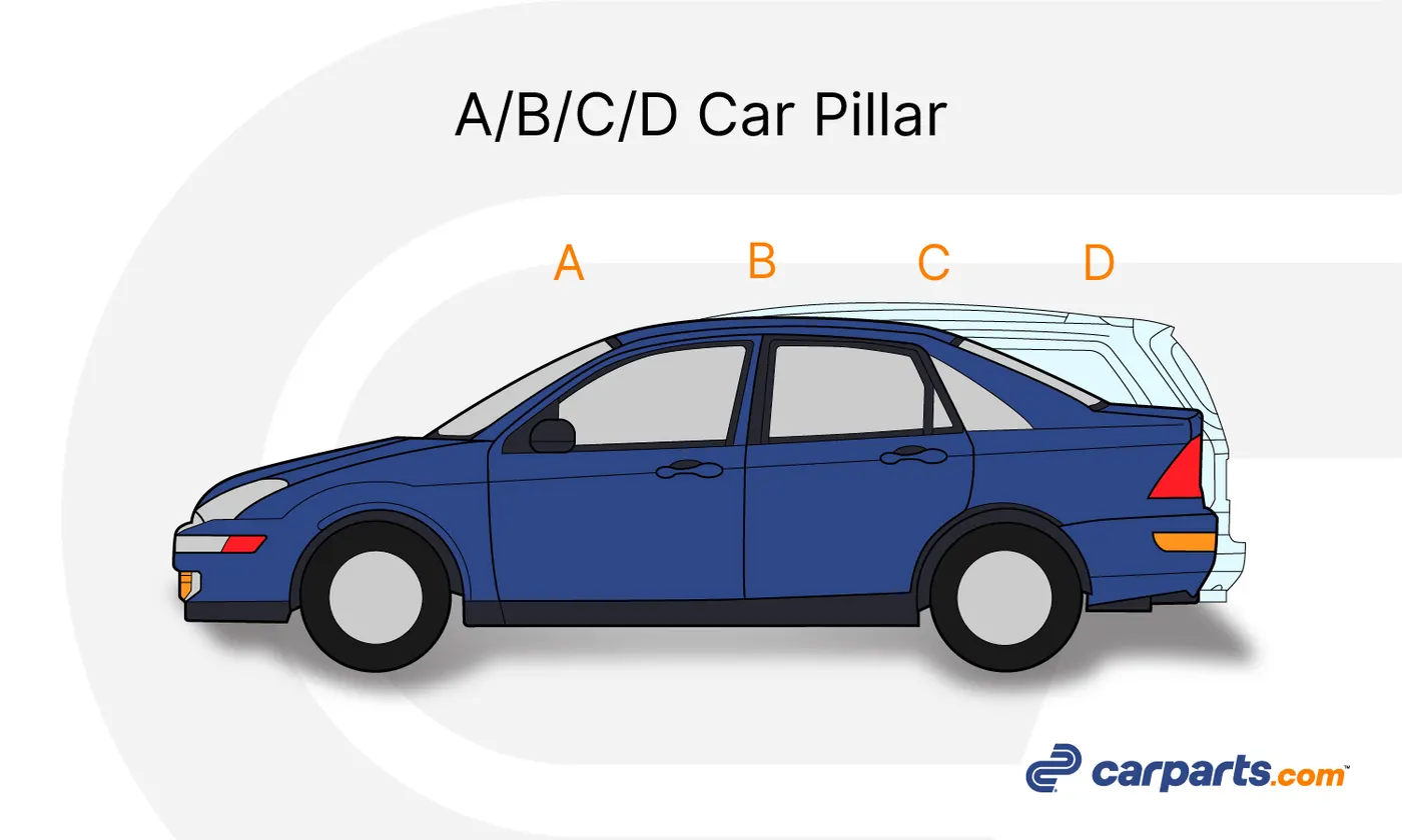
Introduction of A Pillars:
· The A pillars are essential vertical structures located on either side of a vehicle’s windshield, connecting the roof to the body.
· They provide critical support to the roof, ensuring structural integrity and stability during collisions or rollovers. A pillars also house important components like airbags in modern vehicles, enhancing occupant safety.
· These pillars influence the vehicle's aerodynamics and play a significant role in its overall design.
· A major challenge in A pillar design is balancing strength and visibility, as thicker pillars may obstruct the driver’s view, while thinner ones require advanced materials for adequate support.
· A pillars are also crucial for absorbing and redirecting impact forces during accidents, contributing to passenger protection. Their design affects not only safety but also the aesthetic appeal of the vehicle.
· In modern automotive engineering, A pillars showcase the seamless integration of form and function.
Master section:
· A Master Section is a key reference in automotive design, providing detailed cross-sectional profiles of vehicle components. It ensures structural integrity, manufacturability, and compliance with design standards.
· Used extensively in the development of Body-in-White (BIW) parts, master sections define dimensions, geometry, and reinforcements for components like A pillars, roof rails, and door panels. These sections balance factors such as safety, aerodynamics, and functionality.
· Master sections serve as a blueprint for collaboration between design, engineering, and manufacturing teams. For instance, an A pillar's master section specifies thickness and curvature to optimize visibility and crashworthiness.
· By aligning design intent with production feasibility, master sections streamline the development process, ensuring accurate and efficient vehicle manufacturing.
Design guidelines:
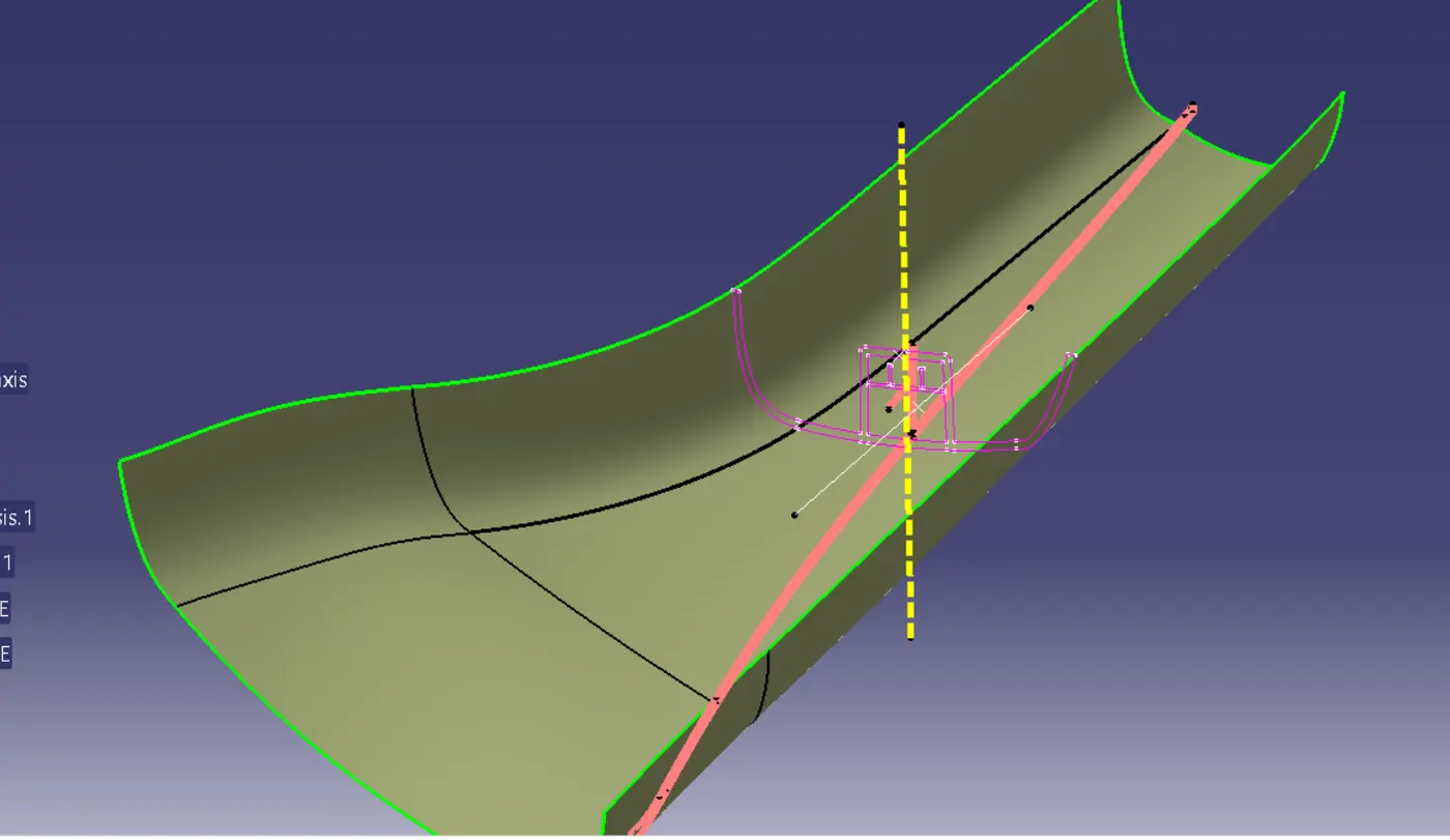
Create the Tooling Axis:
- Analyze the A-class surface to determine the best ejection direction.
- Use intersection lines on YZ and XZ planes to guide the axis creation.
- Generate a bisecting line to finalize the tooling axis.
Develop the B-Class Surface:
- Offset the A-class surface inward by 2.5 mm as specified.
- Extend and trim the surface to match the master section profile.
- Ensure smooth transitions and proper alignment with the A-class surface.
Generate the C-Class Surface:
- If Tooling Axis is Perpendicular: Sweep edges of the A-class surface in the draft direction with a standard angle (e.g., 3°).
- If Tooling Axis is Parallel: Sweep edges perpendicular to the reference surface at 90°.
- Join the C-class surface with the A and B surfaces to create a closed body.
Design the Doghouse:
- Sketch a 25 mm x 25 mm rectangle as the doghouse base.
- Extrude the rectangle with a 2 mm wall thickness.
- Apply a draft angle of 1.5° to 3° for manufacturability.
- Inside draft angle 0.5 degree
- Add fillets to reduce stress concentrations.
- Include ribs or reinforcements if specified in the master section.
Final Validation:
- Perform a draft analysis to ensure all surfaces meet manufacturability criteria.
- Verify the design aligns with the master section and specified guidelines.
Design view of closed surface:
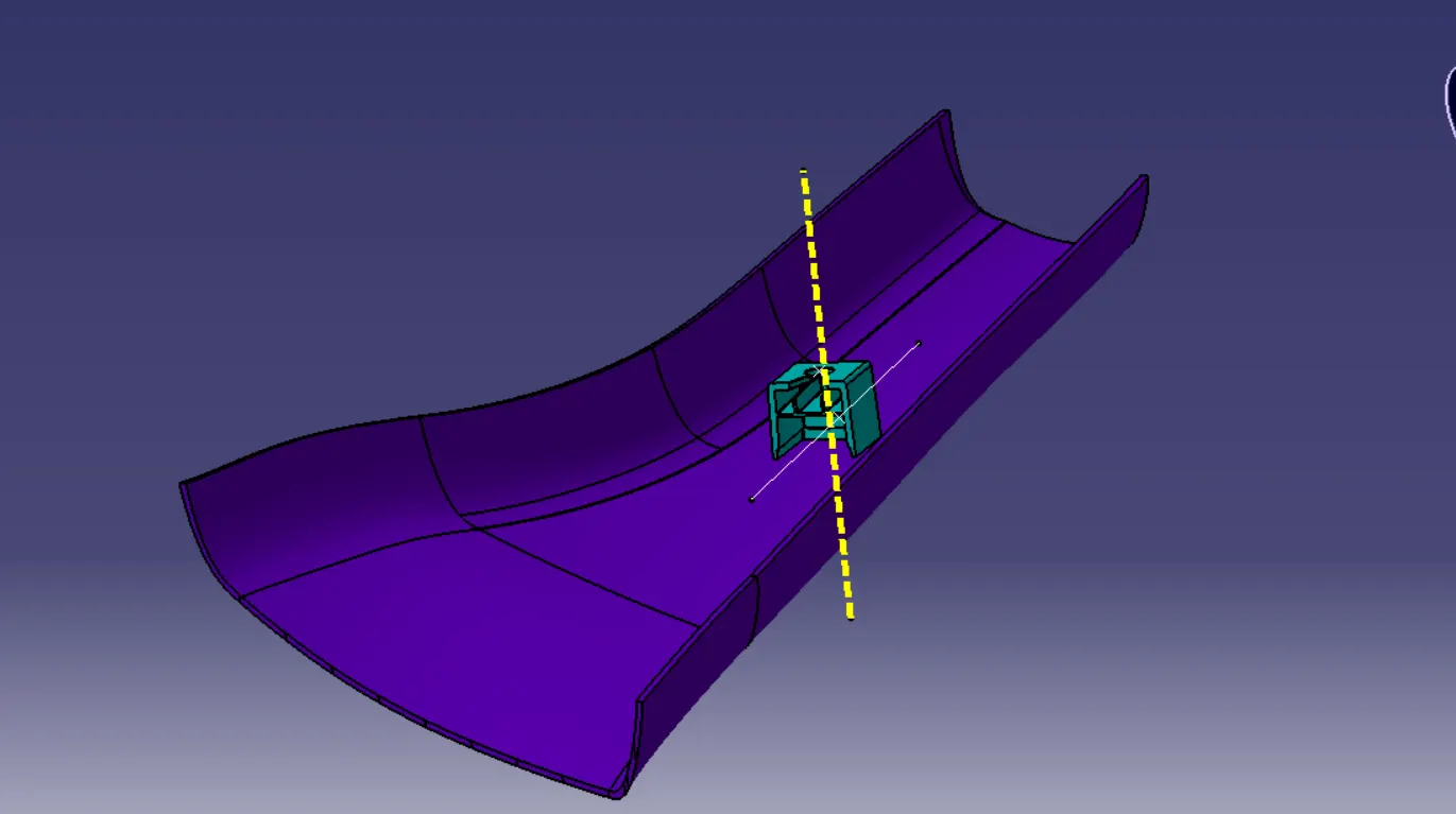
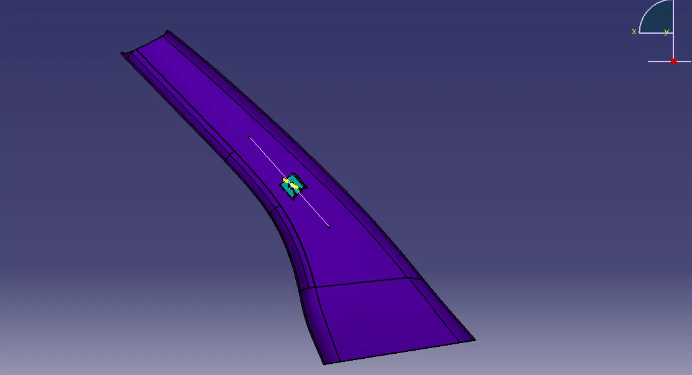
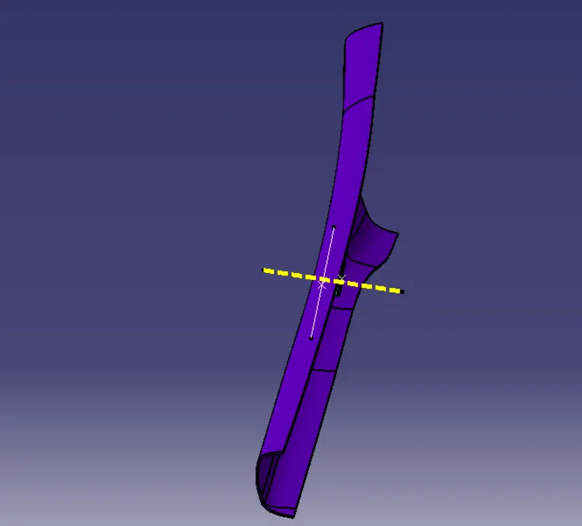
Draft analysis of A class surface:
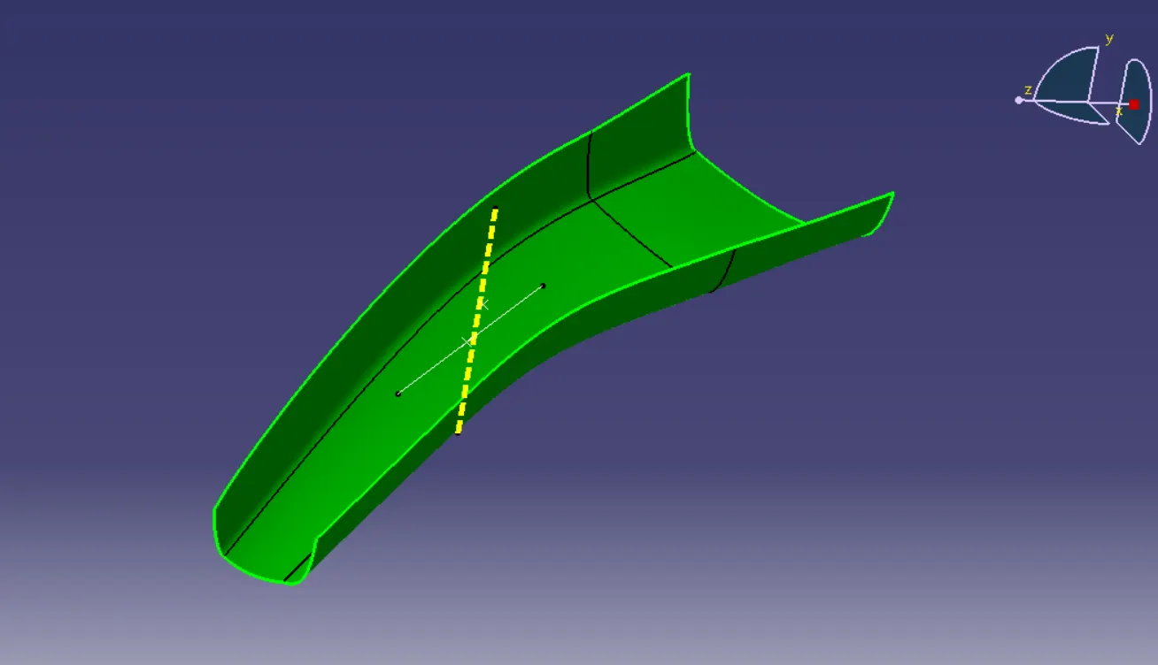
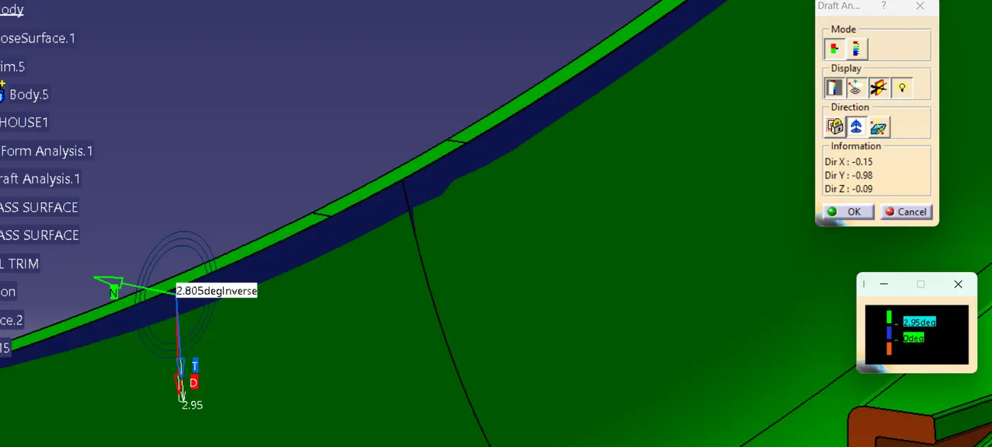
Draft analysis of closed surface:
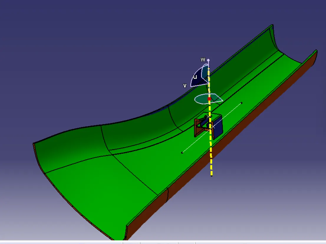
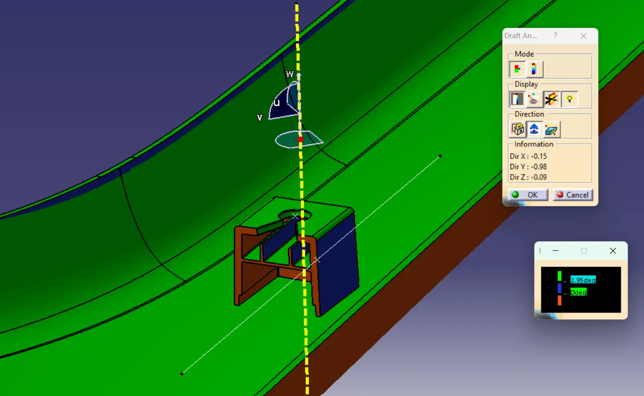
minimum degree is 2.805 degree.
Draft analysis of dog house along tooling axis:
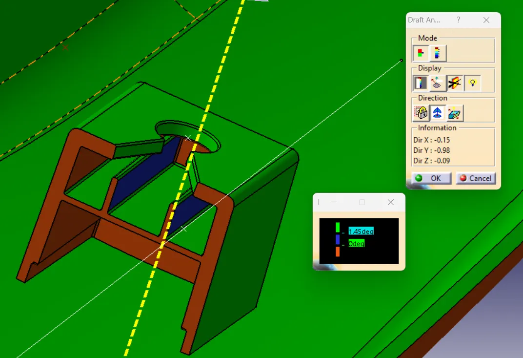
min degree is 1.45
Draft analysis of dog house along surface of doghouse:
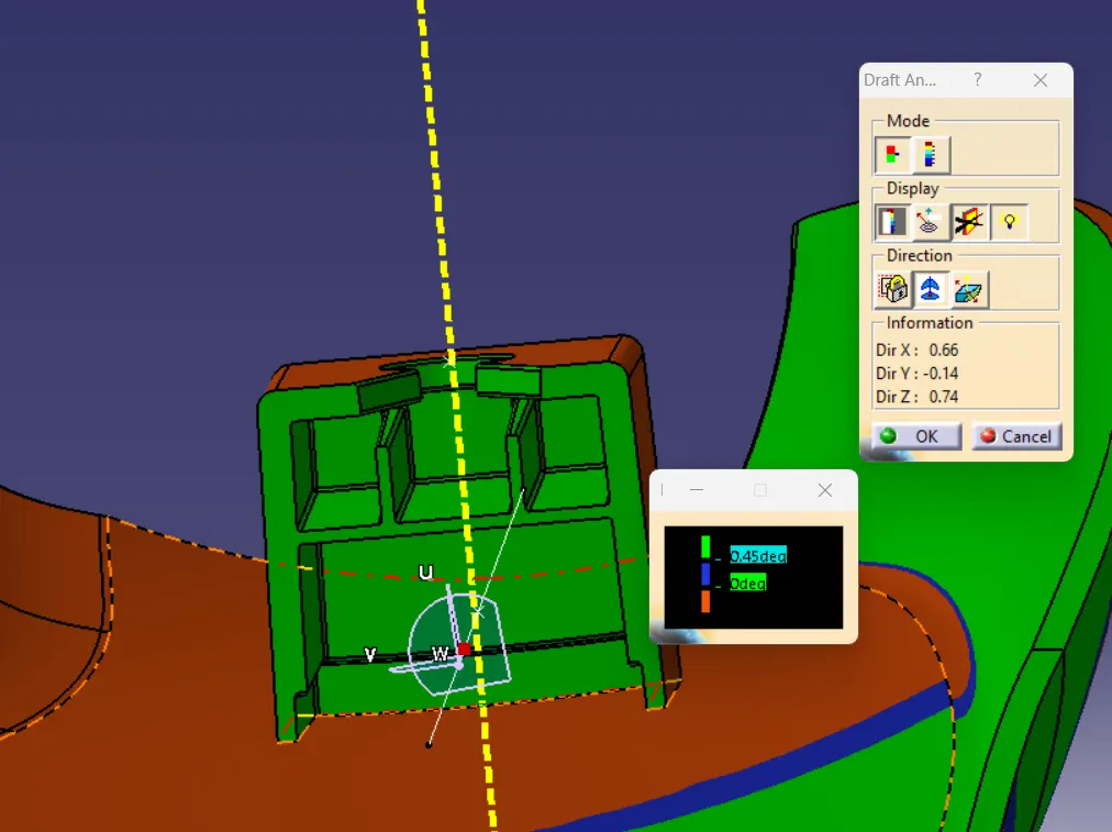
minimum degree inside of the dog house is 0.45
thus i have created the A pillar design with given master section.