Week 11 - Project - A pillar Design with Master Section
The Body Frame Is Mainly Composed Of Floor Longitudinal Beams, Upper Side Beams, Door Sill Beams, And Front Cover, The Rear Beam, A-Pillar, B-Pillar, C-Pillar And Other Load-Bearing Beam Structures Are Composed.
Tooling Axis:
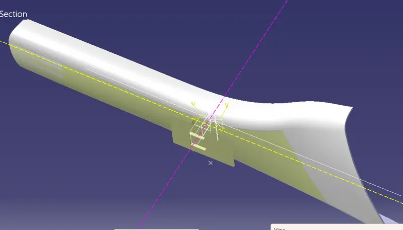
The Given Class A Input Is Analyzed To Envision The Part To Manufacture And Tooling Axis Or Tooling Direction Or Die Line Is The Direction That Molds Pull Apart In Injection Molding. There Are Two Mold Pieces Names Core And Cavity. Thus Tooling Direction Determines Mold Separation And Also Becomes Vital In Developing The Plastic Product Which Is Drafted To Desired Nominal Angle For Feasible Clearance And Ejection Of Final Part From The Mold.
The Steps Followed In Creating Tooling Axis
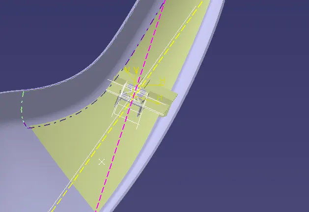
- A Reference Point Is Created Along The Surface Zero And New Axis System Is Created
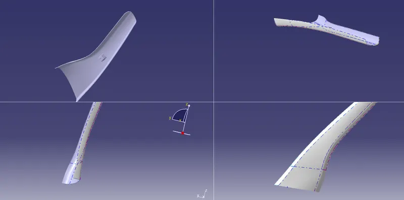
- The X Direction And Y Direction Along The Class A Were Used To Create Tooling Direction
- Finally The Tooling Axis Is Created By Bisecting The Two Lines And It Is Published. Class A Surface As Input Using Surface Operation Commands Class B Is Developed
- The Tooling Axis Determines The Direction Of Class C Boundary Swept With Draft Direction.
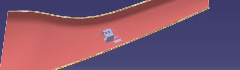
- When Viewing From Tooling Direction Normal All The Parts That Are Drafted Should Be Visible So It Gives An Rough Idea To Determine Product Manufacturing In Injection Molding
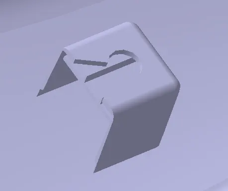
- In B Pillar Model There Are Two Tooling Directions One On Main Tooling And Other On Lifter Side That Is Used To Eject The Parts During Injection Modling
- Lifter Axis Is Used Because The Attachment Feature Is Bounded By Close Walls
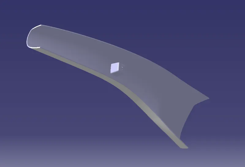
A surface:
Tooling axis:
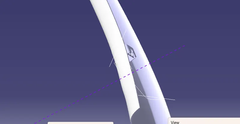
Dog house :
classc:
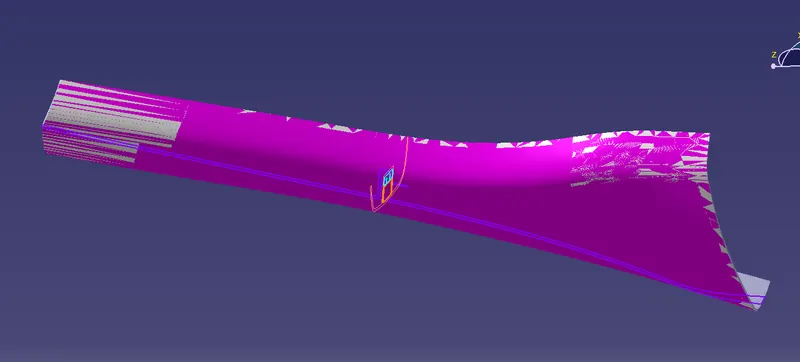
Draft analysis:
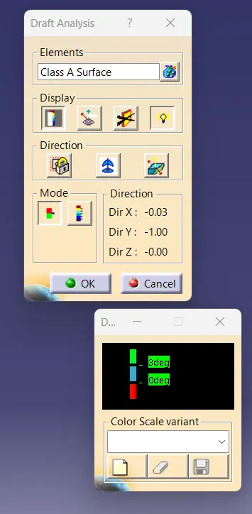
dog house:
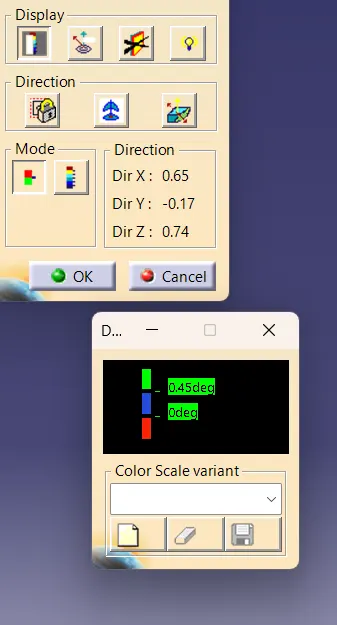
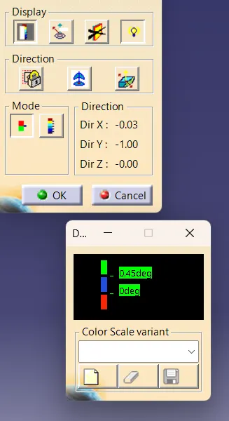
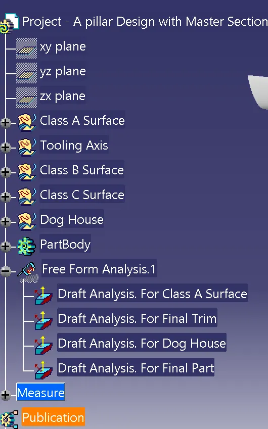
tree structure:
Isometric view: