Week 11: Project 2 - Emission characterization on a CAT3410 engine
AIM : To run the simulation to study Emission characterization on a CAT3410 engine using Converge and achieve the following objectives below:
- Create cut-plan animations showing Soot, Nox and UHC and compare them between the omega and the open-w pistons.
- Compare the imep and power values graphically
INTRODUCTION
METHODOLOGY
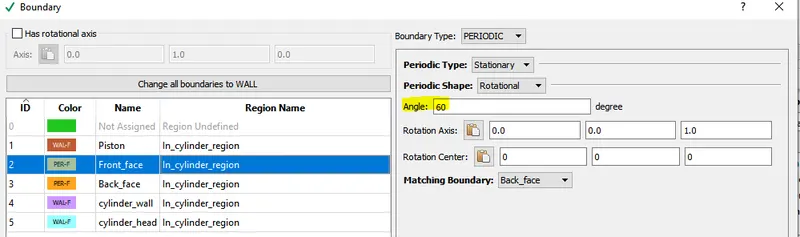
Closed Cycle analysis will not consider valves into account and only a sector of the control volume is used to make analysis to improve computational efficiency.
.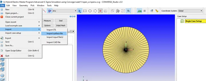
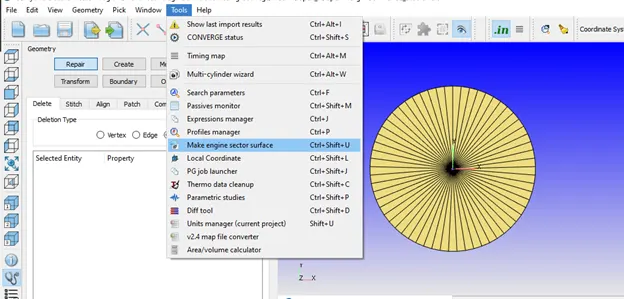
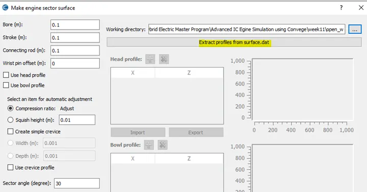
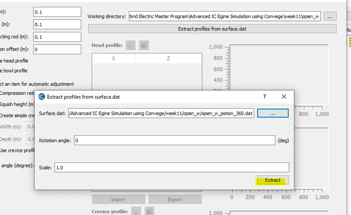
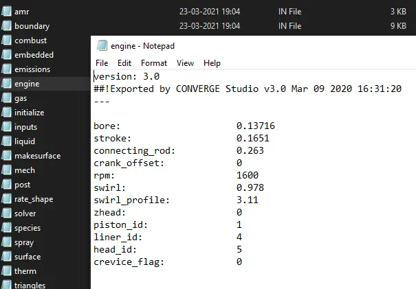
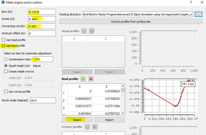
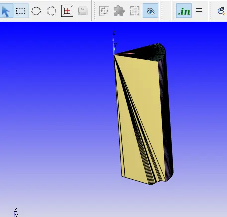
Click Make Surface
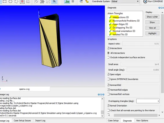
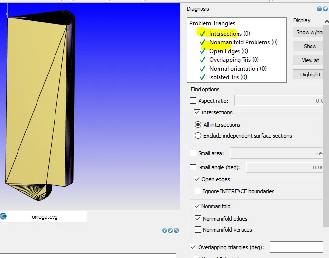
Check for any errors in dynamics Tab
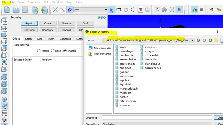
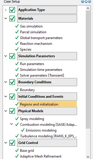
Import Case setup from baseline_input_files
File à Import files --> Input files
Validate All
OMEGA PISTON
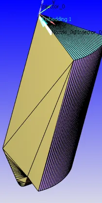
Bowl profile is directly available so go to Tools-> select Make engine sector surface
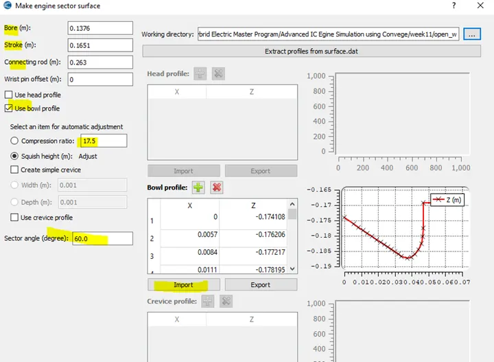
Omega
PROCEDURE:
- Geometry
Case Setup-
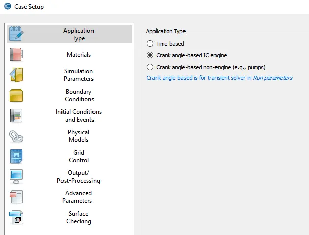
- Application Type
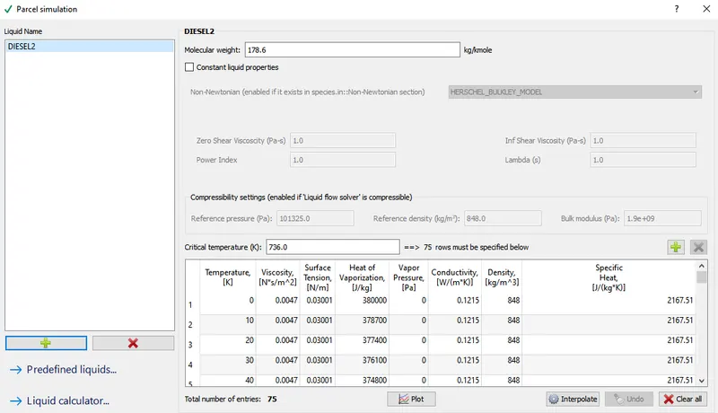
- Materials
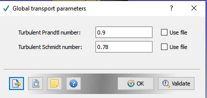
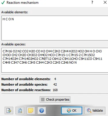
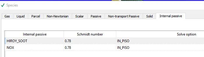
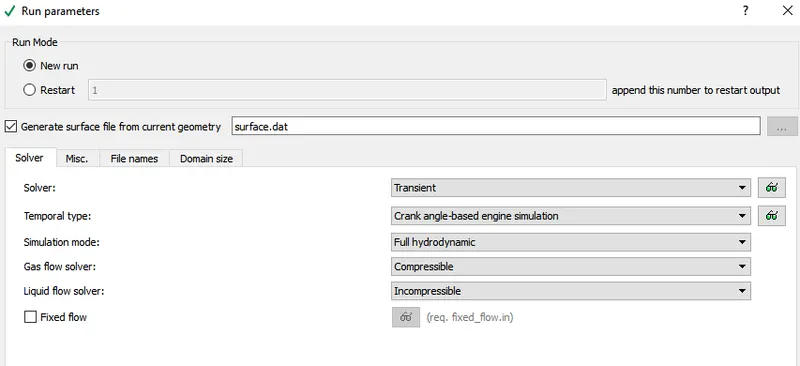
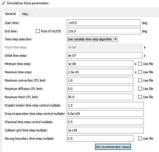
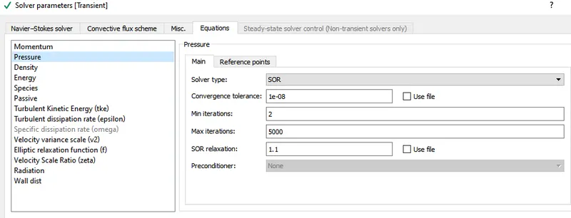
- Simulation Parameters-
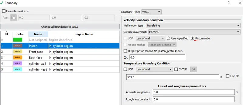
- Boundary Conditions-
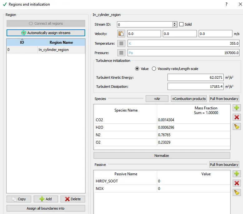
- Initial Conditions and Events:
- Physical Models:
SPRAY MOELLING
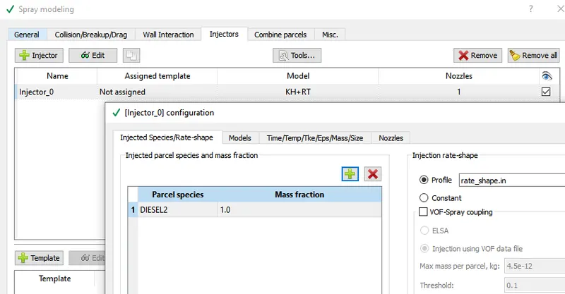
It involves simulation of injection, breakup, vaporization and other defining spray related parameters.
Spray is characterized by liquid penetration length and vapor penetration length. Converge calculates the liquid penetration length by multiplying the total mass of the liquid parcels from nozzle end with fraction obtained the penetrated spray mass. This value is in turn written to the spray.out file.
Forssling model with sourced species C7H16 is used for this simulation.
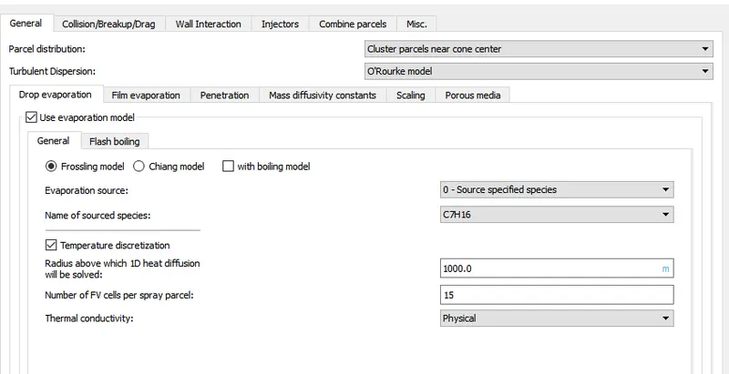
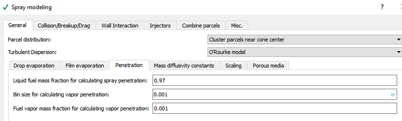
O’Rourke Model is used to find the turbulent dispersion. In order to calculate the vapor penetration length and the liquid fuel vapor mass fraction the following details like liquid mass fraction, bin size and fuel vapor mass fraction needs to be specified
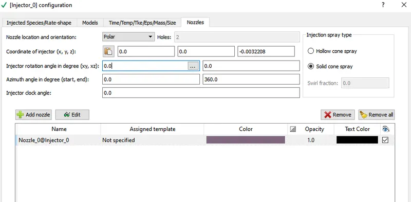
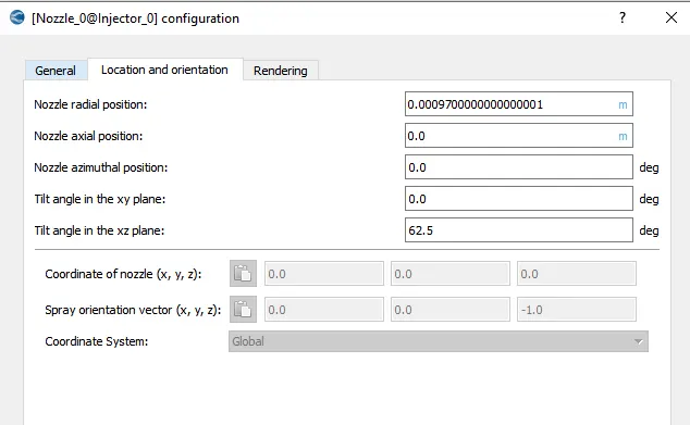
For effective spray of the nozzle inside the cylinder the location of the nozzle and orientation needs to be specified.
CALCULATION OF SPRAY RATE
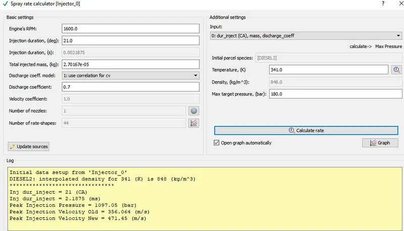
This step involves calculating the spray rate of the injector specified in the previous steps. Parameters like speed, duration of injection, total injected mass and temperature is specified to calculate derived parameters like peak injection pressure, velocity etc. shown in figure.
COMBUSTION MODELLNG:
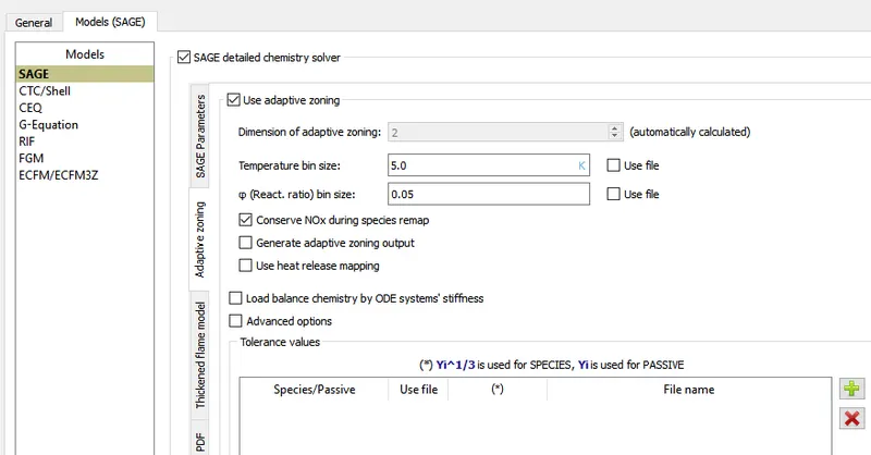
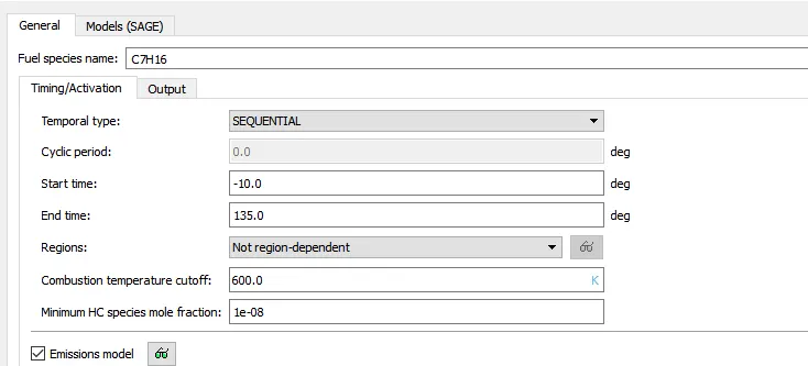
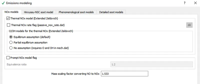
This step involves calculating the reaction rates given chemical solvers based on the principle of chemical kinetics. In this modelling both flow solvers and chemical solvers which works independently but improves the efficacy of solving in short span. SAGE solver is used to predict the possible cases like mixing of fuels (premixed or partially mixed) and emission modelling. Fuel species CH16 is specified in SAGE which is a detailed chemical solver. Performance and emission of an engine is affected by heat transfer. Near Wall measurement is generally used under CFD simulation but there will be some heat loss due to temperature gradient across wall. For accurate prediction of engine heat transfer, wall temperature models are useful for accomplishing heat transfer from the hot gases to all the engine parts, also to the coolant and lubrication oil. It is clear that in PFI engine simulation computational time is large due to complex geometry and solving of both Navier’s stokes and heat transfer equation when we consider the heat transfer effect between fluid and solid surface. Thus, Wall transfer models give more preference to heat transfer and less preference to fluid motion and reactions.
Use total hydrocarbons for formation species is selected to predict the formation of species.
TURBULENCE MODELLING:
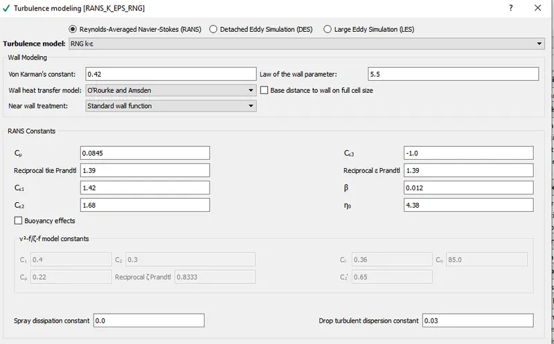
This step involves predicting the effects of turbulence using mathematical models. We use Reynolds Averaged Navier stokes to solve. RNG K- `epsilon`.
BASIC GRID SIZE
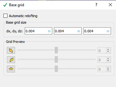
Mesh Size dx=dy=dz=0.04
ADAPTIVE MESH REFINEMENT (AMR)
It involves adaptive increase in the accuracy of a solution within certain turbulent regions of the simulation, dynamically and during specific cycle interval when solution is calculated. It automatically adjusts the grid size at each time step, accumulation of more cells in areas where it requires and eliminates cells that are not required to yield accurate results. AMR ensures that the software can resolve flame fronts and the high velocity flows while keeping the overall cell count minimum.
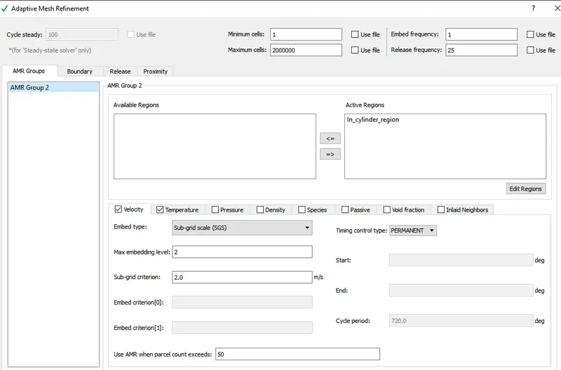
SUB GRID SCALE (SGS) - used for fine grain control of sensitivity of AMR algorithm. SGS modeling is used to represent the effects of unresolved small-scale fluid motions. Significant small scale physical process that occurs at length scales that cannot be adequately resolved on a computational mesh can be represented by SFS.
FORMULA:
Refined Mesh Grid Size= Base Grid Mesh Size/2^(embedded level)
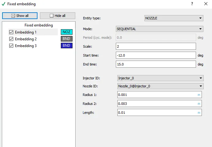
Fixed Embedding:
In order to increase the accuracy of the solution we can improve/refine the mesh size at specific locations using fixed embedding. This will in turn reduce the computation time since only at specific locations we have fine mesh size and other locations we could still maintain coarse mesh.
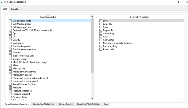
- Post-Processing:
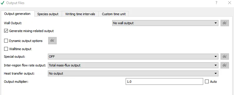
- Output Files:
RESULTS AND DISCUSSION
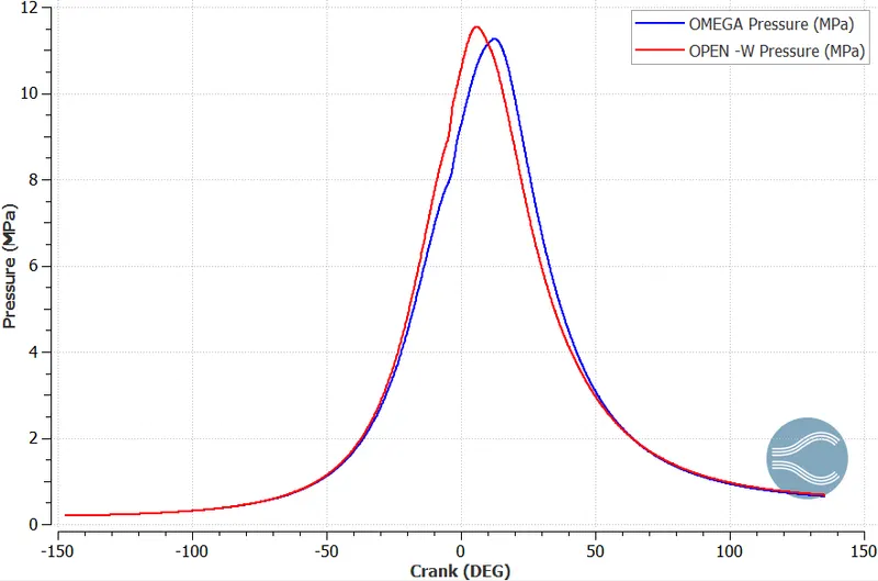
PLOTS – Omega Piston Vs Open W Piston
- Pressure Vs Crank
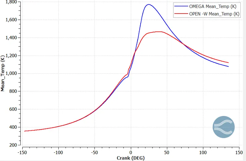
- Mean Temperature Vs Crank
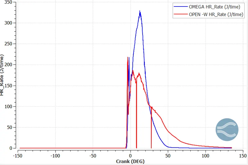
- Heat Release Rate Vs Crank
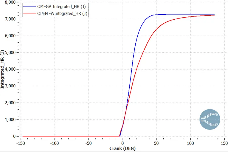
- Integrated Heat Release
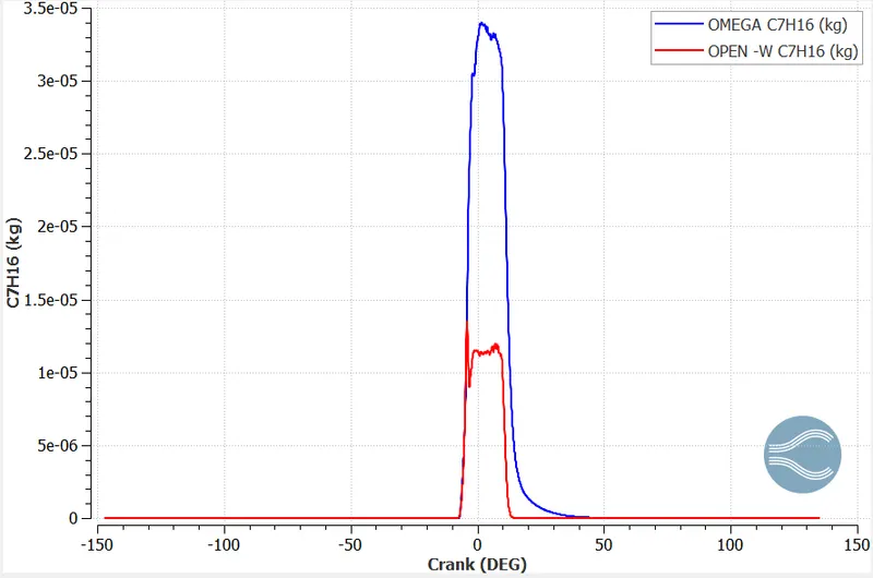
- Gaseous Fuel (C7H16)
Inference: The following conclusions can be made from the above plots,
- Peak pressure for Open-W piston is 11.51 MPa and Omega Piston is 10.59 MPa. Thus Open W piston has higher peak pressure than its counter part due to its geometry as pressure is inversely proportional to its area.
- Mean Temperature for Open-W piston is 1461K and Omega Piston is 1768K. Thus Open W piston has lower mean temperature than its counter part due to its geometry. The advantage of having lower mean temperature would be reduction in NOx but combustion process will be delayed as an effect of liquid spray infringement leading to low performance.
- Heat Release Rate for Open-W piston is 196.61 J/time and Omega Piston is 318.58 J/time . Thus Open W piston has lower Heat release rate than its counter part due to its geometry. This explains why temperature is higher for omega piston as heat release rate is high.
- Integrated heat release rate which explains the integral form of heat release rate and how much energy is released from combustion at a particular point in the plot. It is envisaged from the plot that Open W piston shows slow burning and lower output than Omega Piston resulting in some unburnt beat energy in engine.
- It is envisaged from the plot that some amount of gaseous fuel in omega piston is burnt at end resulting in low temperature increase.
Emissions:
- NOx
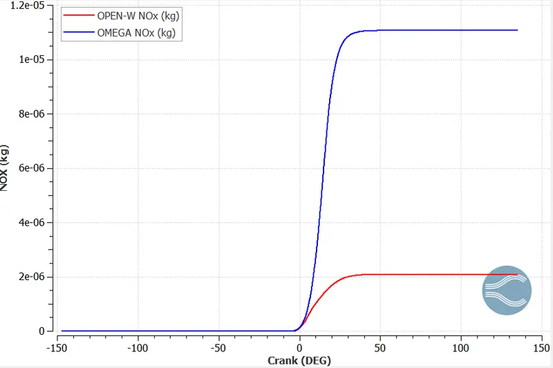
Inference: NOx of Open W piston is low when compared to Omega. Since peak temperature of Open W piston is low then the favorable chances to produce NOx is low. If the requirement is to produce low NOx emission then go for Open W piston.
- Soot
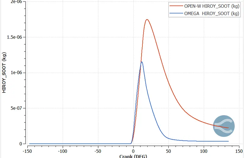
Inference: Black smoke and carbon deposit is referred as soot. It is envisaged from the plot that Open – W piston has high soot formation in comparison to Omega. This is due to low cylinder temperature leading to incomplete combustion of unburnt carbon particles forming soot
3. CO
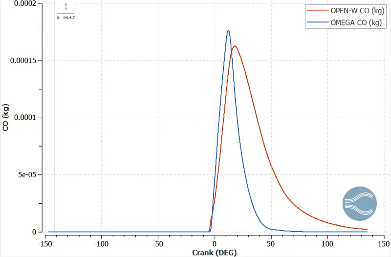
Inference: Factors influencing the formation of CO are incomplete combustion and improper mixing of air and fuel. Open W piston shows improper fuel air mixture decreasing the reaction rate leading to lower in cylinder temperature. Due to incomplete combustion the temperature of propagating flame is low leading to large CO output. Omega piston shows higher CO but it drastically decreases.
4. HC
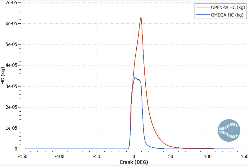
Inference: It is envisaged from the plot that Open W piston having low in cylinder temperature show high Unburnt hydrocarbons in comparison to Omega Piston.
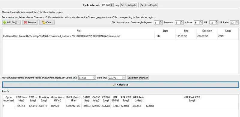
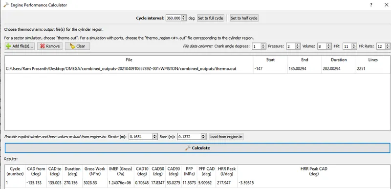
Engine Performance (Power and Torque Comparison Analysis)
omega
| Engine Power & Torque | RPM | 1600 | RPM | |
| RPS | 26.66666667 | RPS | =RPM/60 | |
| DPS | 9600 | degrees/sec | ||
| Time Per Degree | 0.000104167 | sec/degree | =1/DPS | |
| Work done | 3409.28 | Joules | From engine performance Calculator | |
| Combustion Duration | 270.171 | degree | ||
| Time per 270.171 degree | 0.028142813 | sec | =Duration*Time per 720 degree/720 | |
| Power | 121.1421211 | KW | =workdone/Time | |
| Pi | 3.14 | |||
| Torque | 723.38 | Nm | =Power*60/(2*Pi*N) |
Open-W
| Engine Power & Torque | RPM | 1600 | RPM | |
| RPS | 26.66666667 | RPS | =RPM/60 | |
| DPS | 9600 | degrees/sec | ||
| Time Per Degree | 0.000104167 | sec/degree | =1/DPS | |
| Work done | 3028.53 | Joules | From engine performance Calculator | |
| Combustion Duration | 270.156 | degree | ||
| Time per 270.171 degree | 0.02814125 | sec | =Duration*Time per 720 degree/720 | |
| Power | 107.6188869 | KW | =workdone/Time | |
| Pi | 3.14 | |||
| Torque | 642.63 | Nm | =Power*60/(2*Pi*N) |
Inference: Power generated by Omega Piston is higher when compared to the Open W piston.
ANIMATION
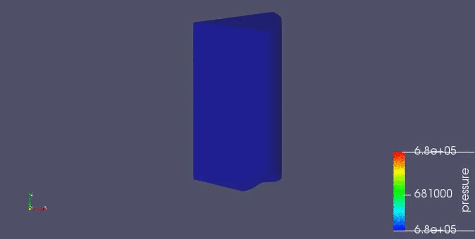
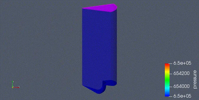
SPRAY WALL INTERACTION
Open-W
Omega
Youtube Animation link:
Inference: When the fuel is injected into the domain it is envisaged that in Open-W piston when the spray impinges on the piston surface, there is not much significant amount of penetration length in comparison Omega piston. This is the major drawback for Open-W piston where majority of fuel is not getting vaporized due to short penetration length. As it is not getting vaporized quickly, fuel requires more time to get evaporated. But we cannot conclude that the Open W piston is detrimental. Thus, Omega Pistons shows good vaporization due to its proper and effective penetration characteristics.
CONCLUSION:
Combustion simulation was performed on CAT 3410 engine with two different pistons using converge and following conclusions were made:
Omega piston profile is better than Piston -W due to the following aspects:
- Effective fuel penetration length in comparison to its counter
- Higher Power
- Complete combustion of Fuel
- Low HC ,Soot, CO but higher NOx