week-11 Joint creation and Demonstration
Objective:
Using the manual (*CONSTRAINED_JOINT keyword) demonstrate spherical, revolute, cylindrical, and translational joints between two rigid bodies and two deformable bodies.
Procedure
A joint is created using an even number of nodes, out of which every pair has the same position (XYZ coordinate). These nodes should belong to the bodies between which the joint operation
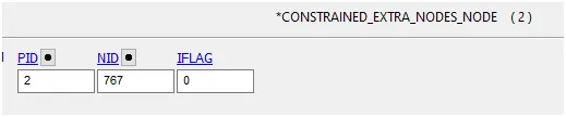
We use *CONSTRAINED_EXTRA_NODES and *CONSTRAINED_NODAL_RIGID_BODY to create joints between rigid and deformable bodies respectively.
Rigid Body: Once you create the nodes at the required location, use *CONSTRAINED_EXTRA_NODES to include those nodes to the respective rigid bodies.
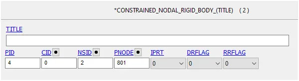
Deformable Body: The nodes should be part of a *CONSTRAINED_NODAL_RIGID_BODY which has some shared nodes with the deformable body.
Revolute joint
A revolute joint is one degree of freedom kinematic pair used frequently in mechanisms and machines. The joint constrains the motion of two bodies to pure rotation along the common axis
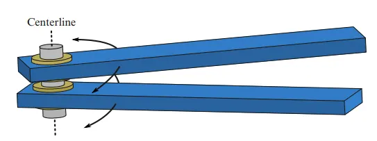
Create a geometry for Revolute joint for rigid body
These geometry we can use for both the rigid and deformable bodies , first two separate shell element are created using Mesh and element > shape mesher>4N shell > assign the coordinate according P1,P2,P3 and P4 and create it
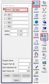
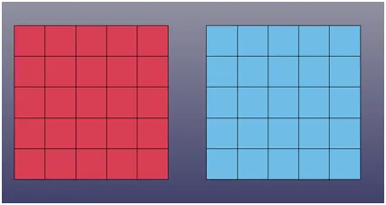
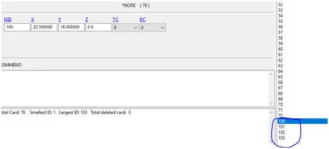
Node edit > create 4 nodes
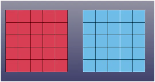
Create extract node id 100,101,102,103 respectively
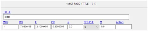
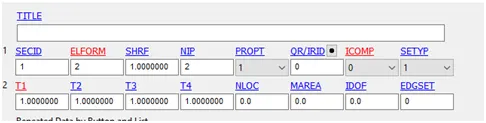
Assign Material and section to respective part id
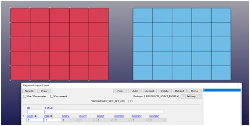
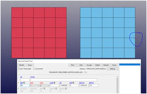
Apply boundary condition at one end of the shell part
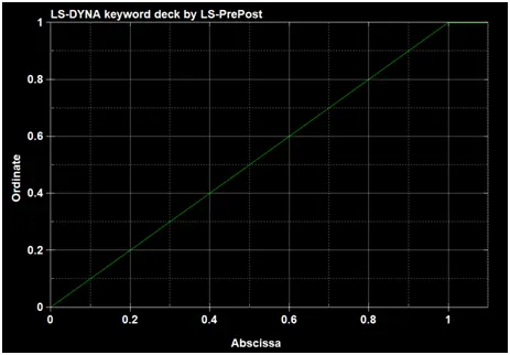
Define load curve
Joint with two deformable bodies
These geometry we can use for both the rigid and deformable bodies , first two separate shell element are created using Mesh and element > shape mesher>4N shell > assign the coordinate according P1,P2,P3 and P4 and create it
Assigned with shell section and material properties (“MAT_ELASTIC) to the parts
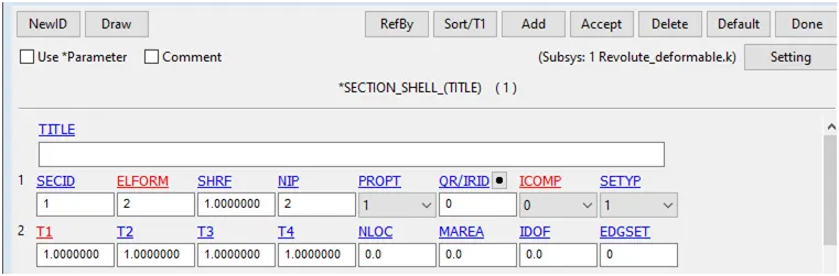
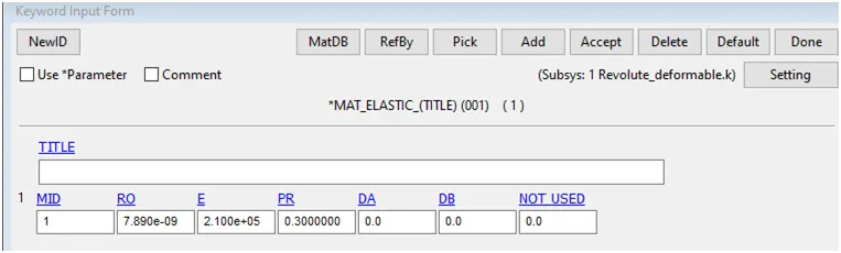
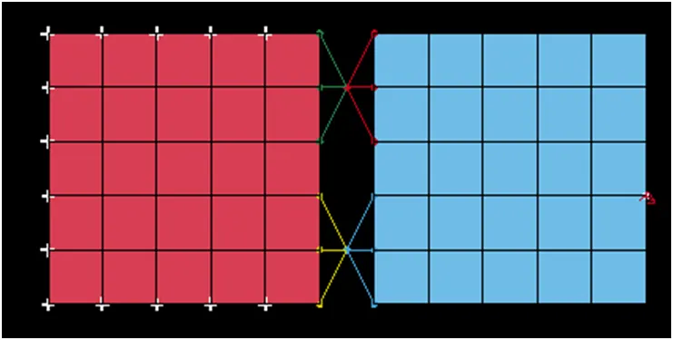
.CNRB is created for the Right plate is fixed and the master node for the first CNRB is created at midpoint of two plate
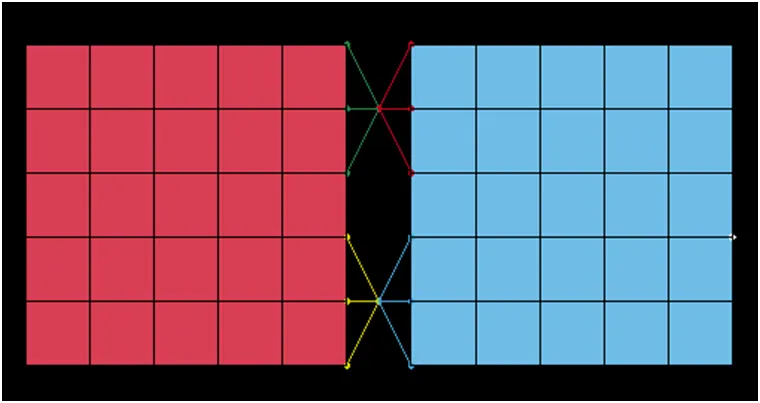
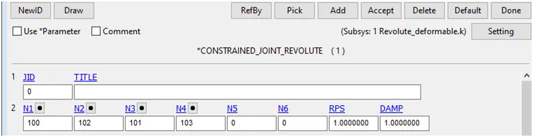
The Revolute joint is created using “CONSTRAINED_JOINT_REVOLUTE” card with nodes N1 and N2 has two master nodes for the first pair of CNRB for right and left plate and nodes N3 and N4 has the two master node for second pairs of CNRB for right and left plate.
Boundary condition Spc is fixed at left plate
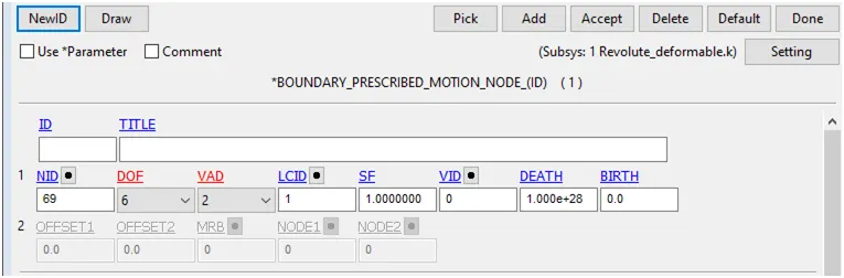
Boundary prescribed motion a node on the left plate along Y rotation – axis
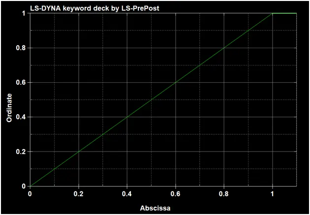
LCID curve is attached with Boundary prescribed motion displacement vs time (0,0) (1,1) and (1.1,1)
Spherical joint
Joint with two rigid bodies
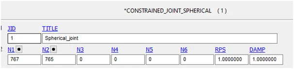
A spherical joint is used for allowing free rotation in two planes at the same time while preventing translation in any direction, including rotating in those planes
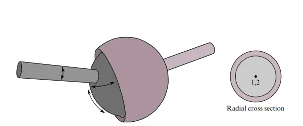
Rigid body
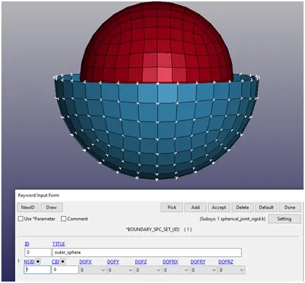
These geometry we can use for both the rigid and deformable bodies , first two separate shell element are created using Mesh and element > shape mesher> spherical shell
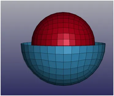
Assign Material (MAT_RIGID)and section to respective part id
Create the node set list
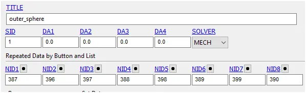
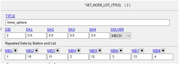
Create extra node

Create joint spherical
Assign velocity

Joint with two deformable bodies
These geometry we can use for both the rigid and deformable bodies , first two separate shell element are created using Mesh and element > shape mesher> spherical shell
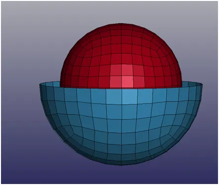
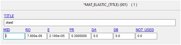
Assign Material (MAT_ELASTIC)and section to respective part id
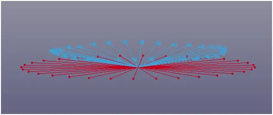
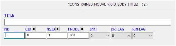
CNRB is created for Half sphere and sphere parts and master node for first and second CNRB is created at the midpoint of sphere.
Cylindrical joint
Cylindrical joint is a two degree of freedom kinematic pair used in mechanisms. It provide a single axis sliding function as well as asinglerotation ,providing a way for two rigid bodies to translate and rotate it freely
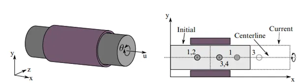
This joint is derived from the rotational joint by relaxing the constraints along the centreline,This joint is admits relative rotation and translation along the centreline.
Joint with two rigid bodies
Procedure for Rigid body Cylindrical joint
The two parts for cylindrical joint are created using Element and mesh > shape mesh > Shell cylinder .
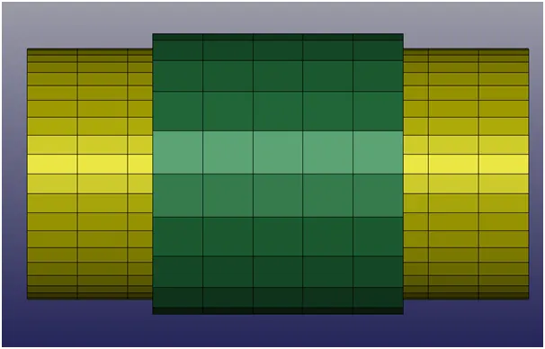
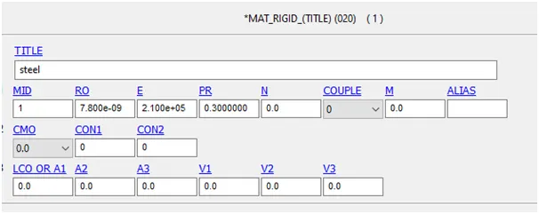
Assigned the parts with shell section and material properties (“MAT_RIGID”) to the parts
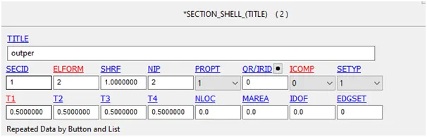
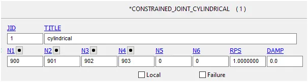
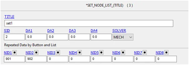
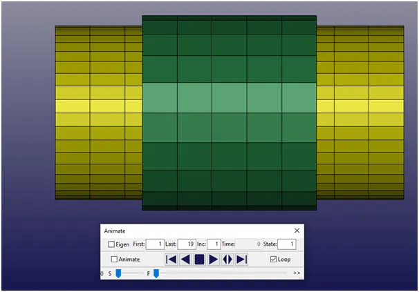
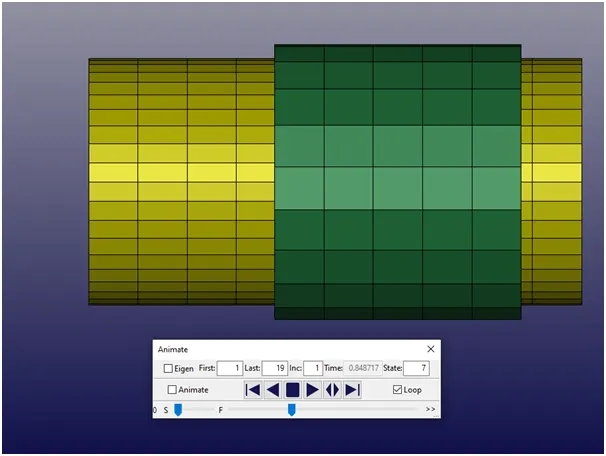
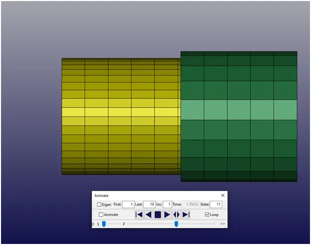
The Four node are created at the centreline of the cylinder where the nodal pair are 900,903 and 901,902 coincide with each nodes .A node set created where 900 and 903 are grouped to fixed one and 901 and 903 grouped to movable body . further nodes of moving and fixed bodies are assigned.
Two node set are created
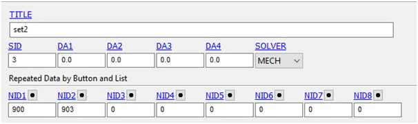
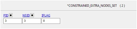
The two Extra node set where created for inner and outer part

Joint with two deformable bodies
The two parts for cylindrical joint are created using Element and mesh > shape mesh > Shell cylinder
Assigned the parts with shell section and material properties (“MAT_ELASTIC” ) to the parts
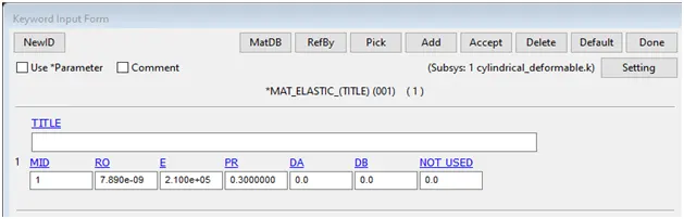
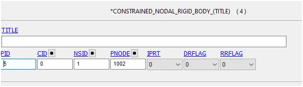
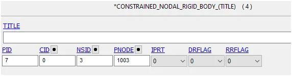
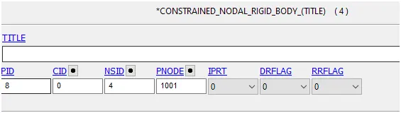
CNRB is created for outer cylinder and the master node for the first CNRB is created at the center of the cylinder.
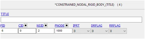
Created CNRB for the inner cylinder (moving part but make sure the master node of the second CnRB coincide with the first CNRB which is created for the outer cylinder
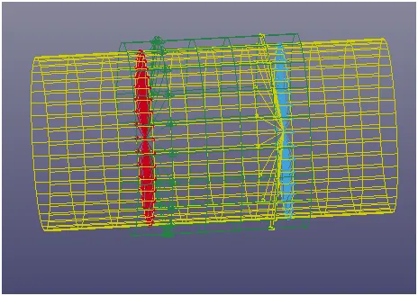
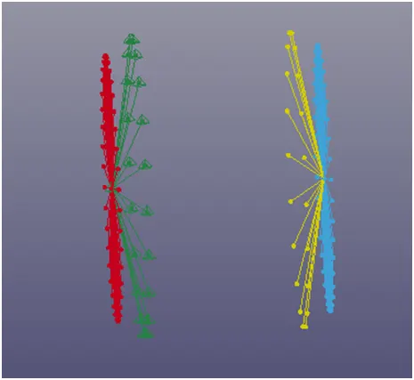
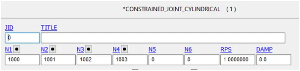
The cylindrical joint is created using *CONSTRAINED_JOINT_CYLINDRICAL “ card with node N1 and N2 has an mater nodes for first pair of CNRB for inner and outer cylinder and N3,N4 has two slave node for second pair of CNRB for inner and outer cylinder
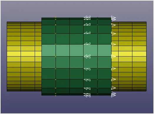
The initial velocity of 15 mm/ms is assigned to outer part towards X direction and -10 mm/ms at X rotational direction
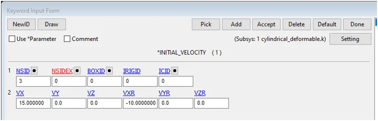
CONSTRAINED _JOINT_CYLINDRICAL is created
 .
.
Translational joint
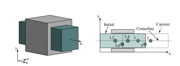
A Translational joint provides a linear sliding movement between two bodies
This is a cylindrical joint with the third pair of off-centerline nodes which restrict rotation , Aside from translation along the centreline ,two rigid bodies are stuck together.
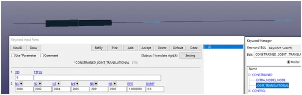
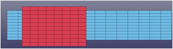
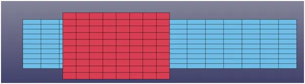
Joint with twoRigid bodies
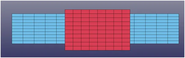
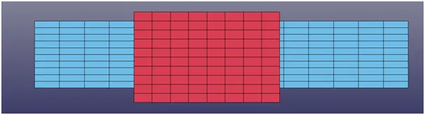
Two parts are created using mesh and element >shape function >shell rectangle.
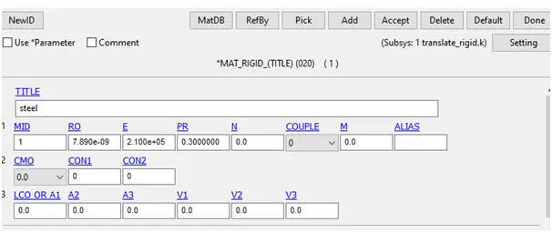
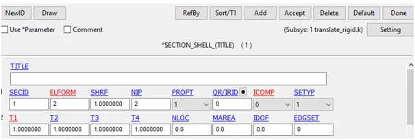
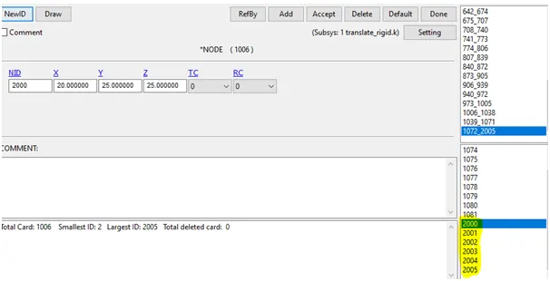
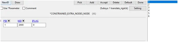

Joint with two deformable bodies
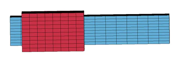
Two parts are created using mesh and element > shape function >shell rectangle .
Assign with shell section and material properties as “MAT_ELASTIC”
CNRB is created for outerbox and inner box for first and second nodes for the first , second and third are created at the centerline of the box.
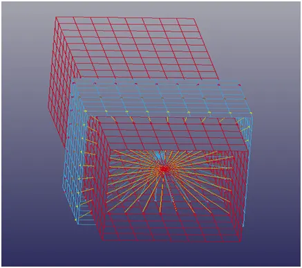
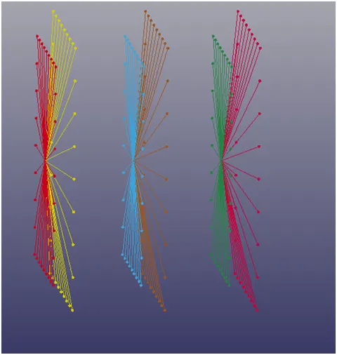
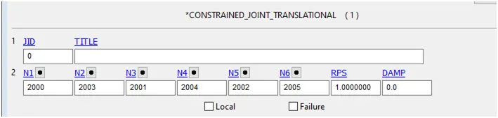
“CONSTRAINED_JOINT_TRANSLATION “ is created as 2000,2003,2001,2004,2002 and 2005 respectively
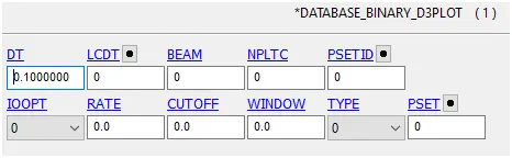
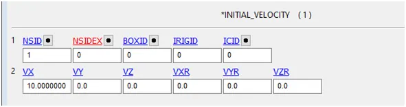
“INITIAL_VELOCITY” is created at towards X direction
Conclusion
From these Assignment I had learn to create and represent the joint creation of Cylindrical, Revolute, Translational and Spherical joint between rigid and deformable bodiesin details with the help Ls-Dyna manuals.