week-11 Joint creation and Demonstration
Objective:
To Model joints of translational, revolute, cylindrical, and spherical joints. The joints are to be modeled by using
- Rigid material
- Deformable material with CNRB
Revolute Joint:
A revolute joint is one degree of freedom kinematic pair used frequently in mechanisms and machines. The joint constrains the motion of two bodies to the pure rotation along a common axis.
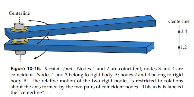
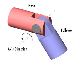 Let's assume, Nodes 1 and 2 are coincident from base here; nodes 3 and 4 are coincident of follower. Nodes 1 and 3 belong to Base; nodes 2 and 4 belong to follower. The relative motion of the two rigid bodies is restricted to rotations about the axis formed by the two pairs of coincident nodes. This axis is labeled the “centerline”.
REVOLUTE JOINT USING RIGID BODY
- Element & Mesh > Shape Mesher > Entity > 4N Shell > Give (x,y,z) co-ordinates
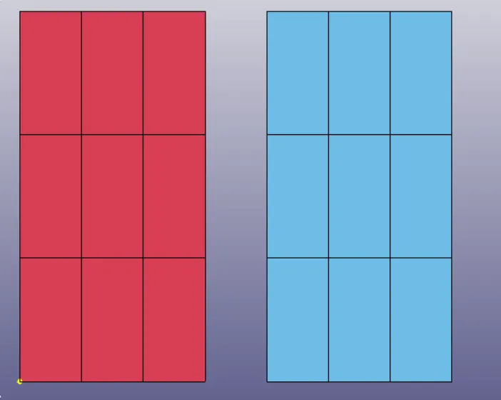
- Material property is given as steel & Section property is assigned
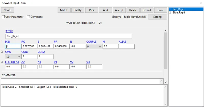
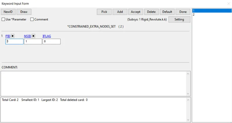
- To create between mid node and the Rigid part *CONSTRAINED > EXTRA_NODES_SET is to be defined
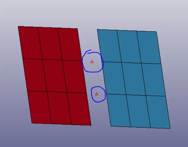
- First, four nodes are created at the middle between two parts.
- Element tools > Edit Node > Create > By two
- where the nodal pairs N1, N2 are coinciding and N3, N4 coincide with each other the first and second pair of nodes are aligned with the centreline of the box.
- The nodes N1, N3 are constrained to the right plate, and nodes N2, N4, and are left plate using the CONSTRAINED > EXTRA_NODES card.
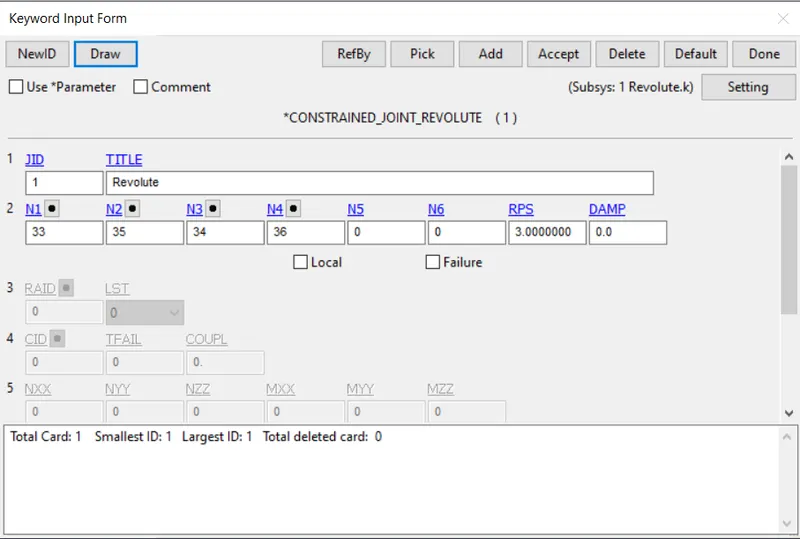
- The Revolute joint is created using CONSTRAINED > JOINT_REVOLUTE card with nodes N1 and N3 has the two master nodes for the First pair of CNRB for Right and Left Plateand nodes N2 and N4 has the two master node for the second pair of CNRB for Right and Left Plate
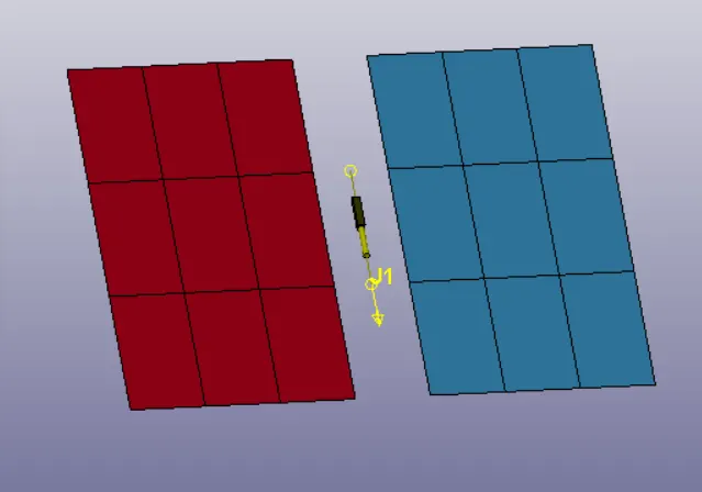
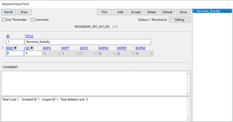
- SPC is created and all the DOF for the right plate nodes are constraint
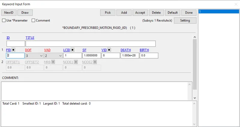
- Boundary prescribed motion a node on the left plate along Z-axis
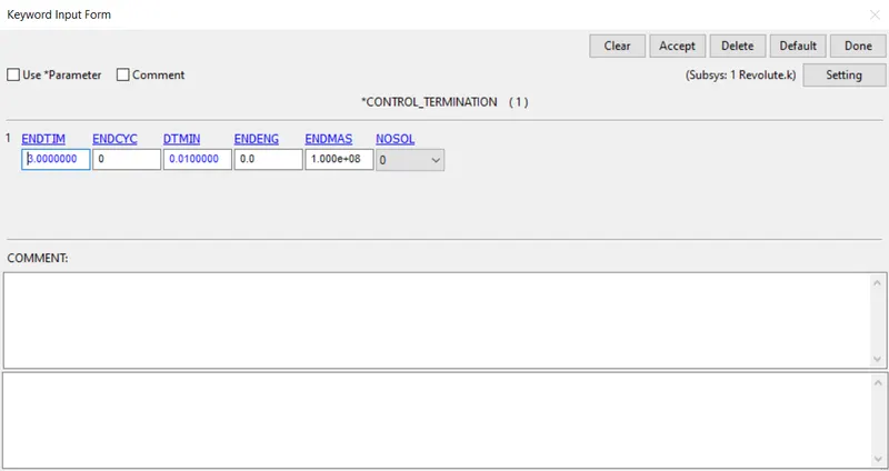
- And default control card to run a simulation is created
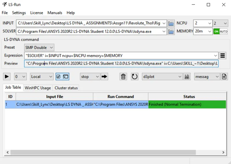
- Open LS- RUN, Input the file Rigid_Revolute.k
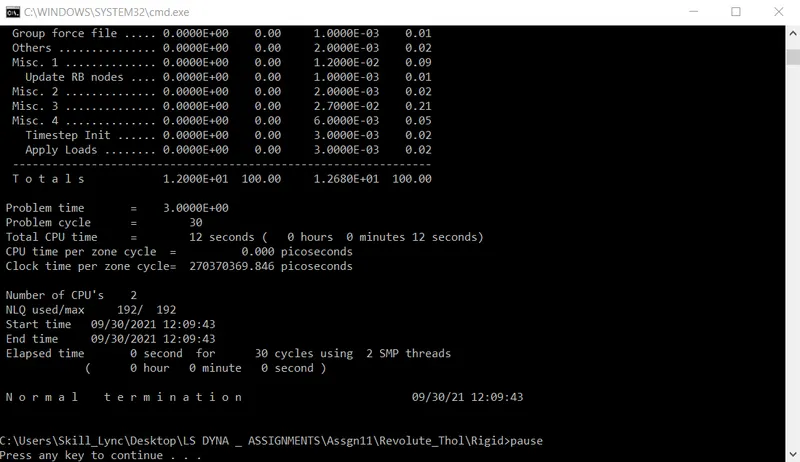
Result

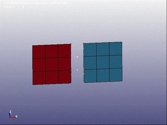
REVOLUTE JOINT USING DEFORMABLE BODY :
- Element & Mesh > Shape Mesher > Entity > 4N Shell > Give (x,y,z) co-ordinates
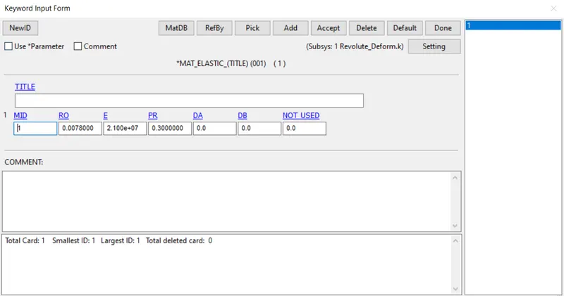
- Material property is given as rubber & Elastic & Section property is assigned
To create CNRB between two parts
- First, four nodes are created at the middle between two parts.
- Create entity > Constraints > CNRB
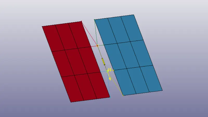
- where the nodal pairs N1, N2 are coinciding and N3, N4 coincide with each other the first and second pair of nodes are aligned with the centreline of the box.
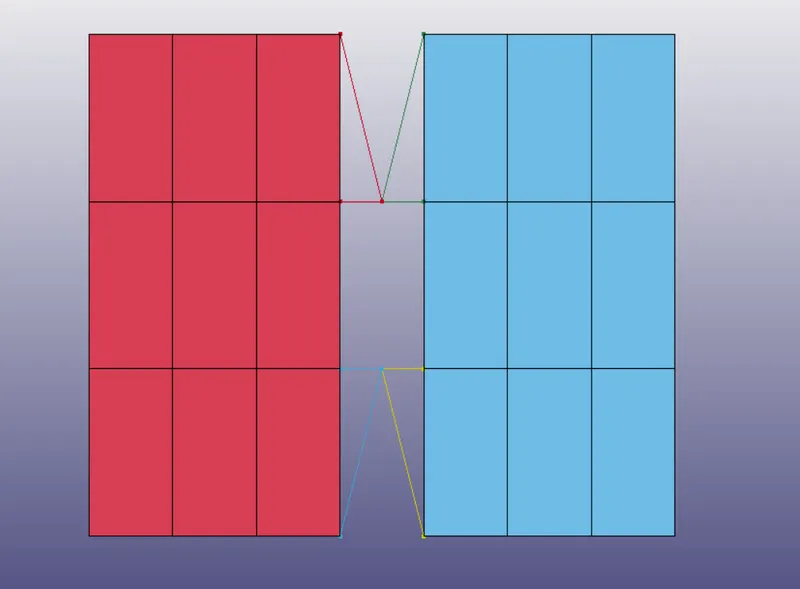
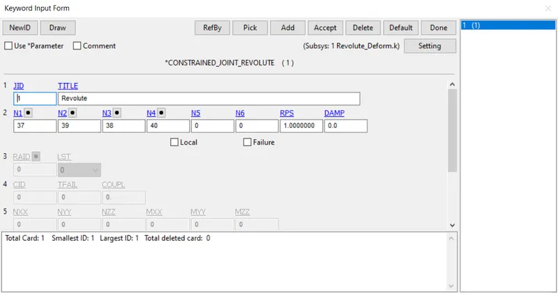
- The Revolute joint is created using CONSTRAINED > JOINT_REVOLUTE card with nodes N1 and N3 has the two master nodes for the First pair of CNRB for Right and Left Plateand nodes N2 and N4 has the two master node for the second pair of CNRB for Right and Left Plate
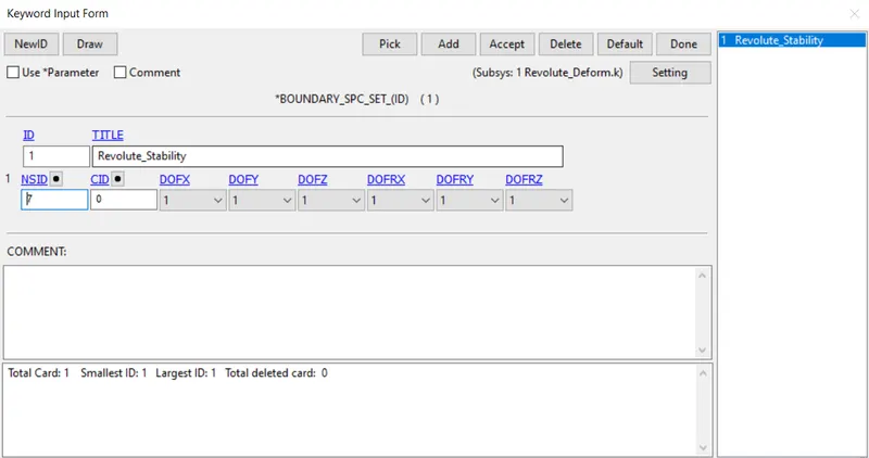
- SPC is created and all the DOF for the right plate nodes are constraint
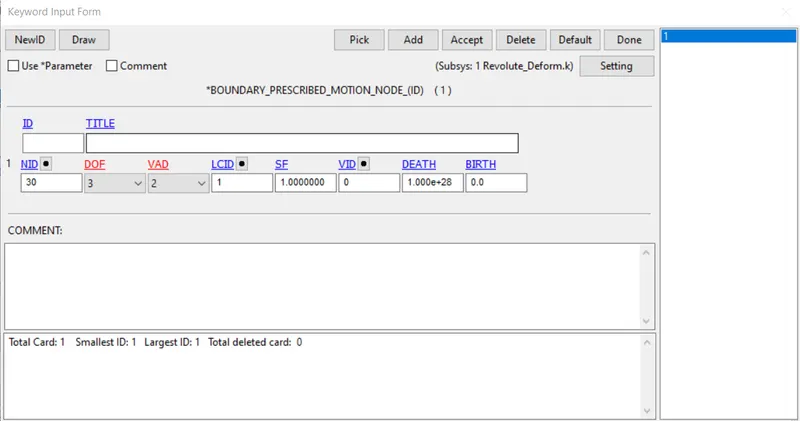
- Boundary prescribed motion a node on the left plate along Z-axis
And default control card to run a simulation is created.
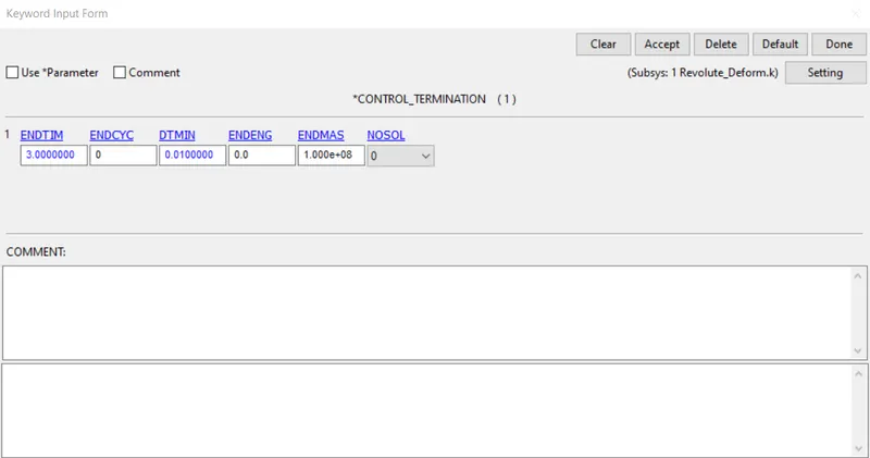
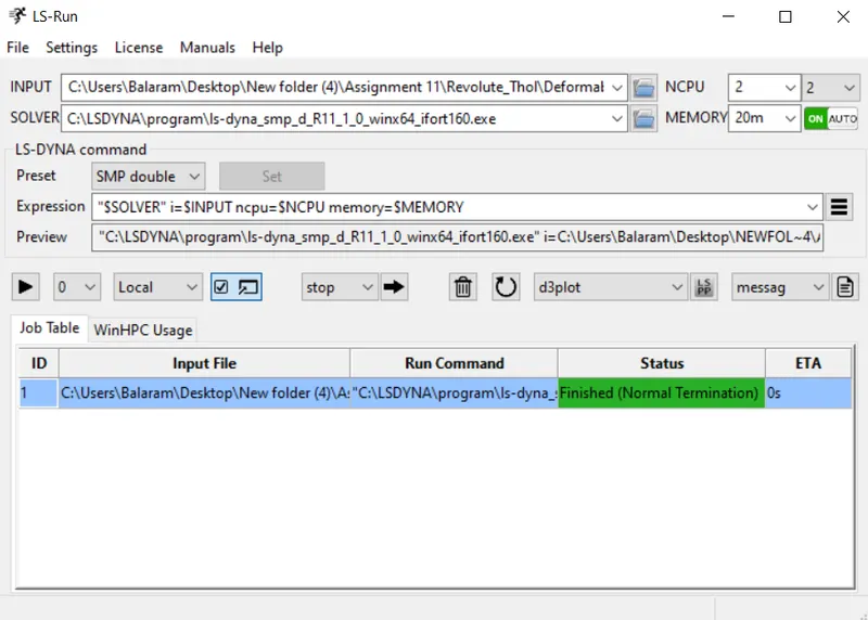
- Open LS- RUN, Input the file Rigid_Revolute.k
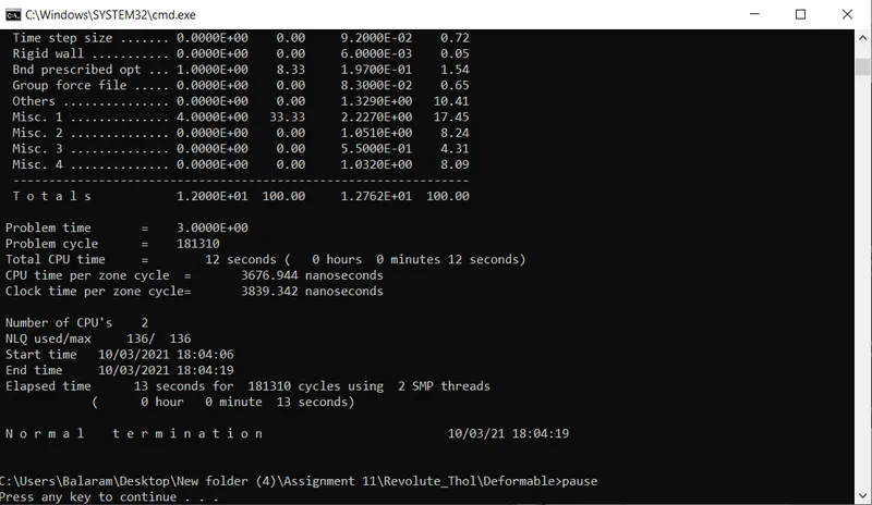
Result
SPHERICAL JOINT USING DEFORMABLE BODY :
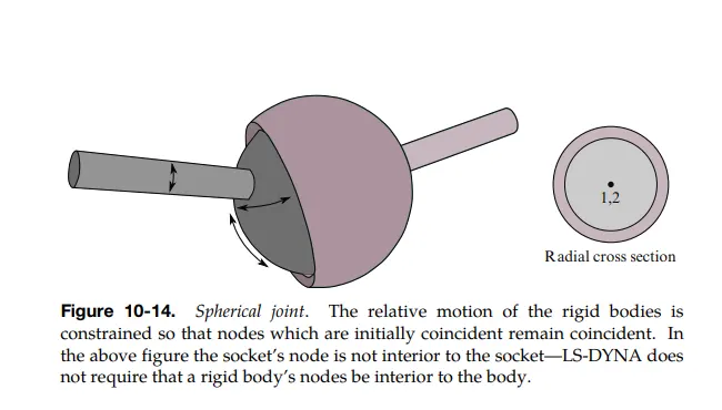
SPHERICAL JOINT USING RIGID BODY
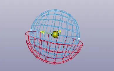
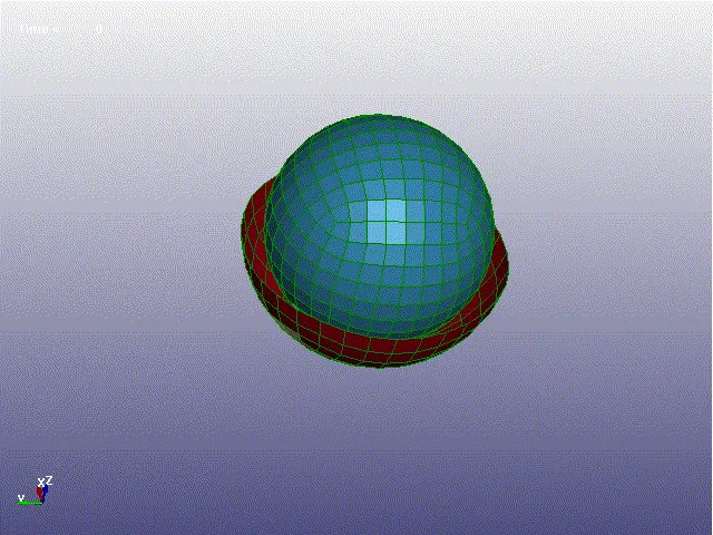
- To create spherical shell - Mesh > Shape Mesher > Sphere Shell
- One shell with Bigger Radius and another one with less smaller
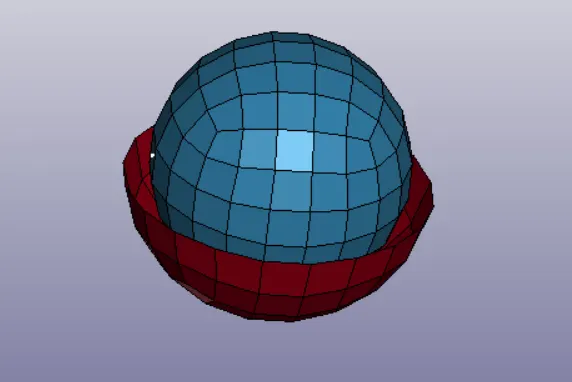
3. Create 2 nodes at the center and assign each node to belong to each part Individually
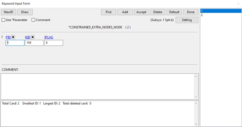
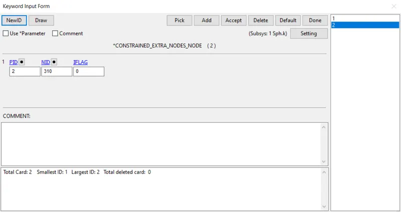
CONSTRAINED EXTRA NODE:
- Centre Node of the Sphere shell is assigned to the centre node in both sphere
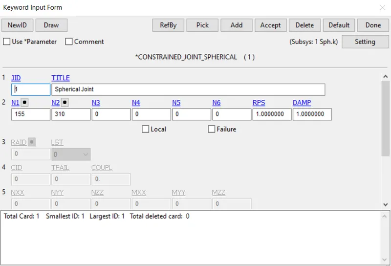
CONSTRAINED JOINT SPHERICAL
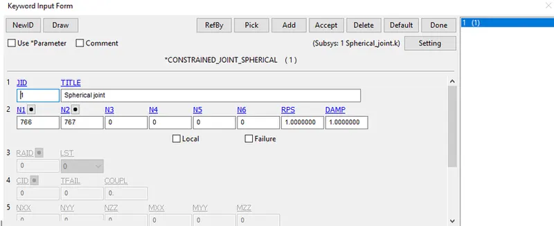
Constrained_Joint_Spherical card is assigned with the coinciding Node Id
MATERIAL
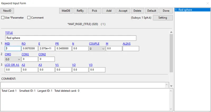
The material properties of steel is assigned.
INITIAL VELOCITY:
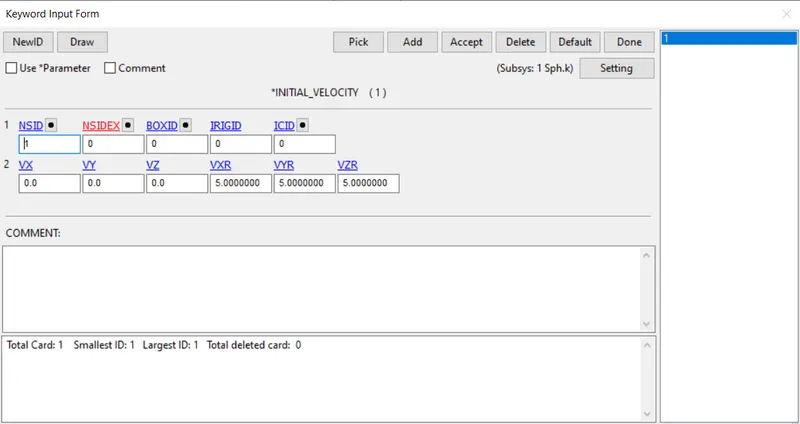
Initial velocity is assigned to roll in x,y,z axis 5mm/ms
SPC : The Outer Sphere Is Constrained In All DOF's
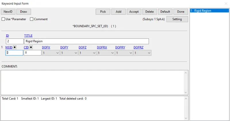
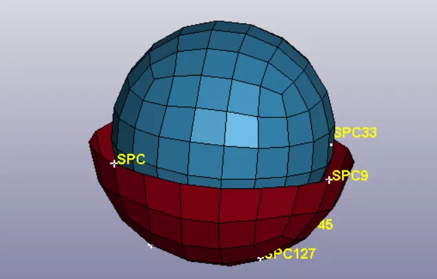
All other keywords are Assigned as same in the Previous One
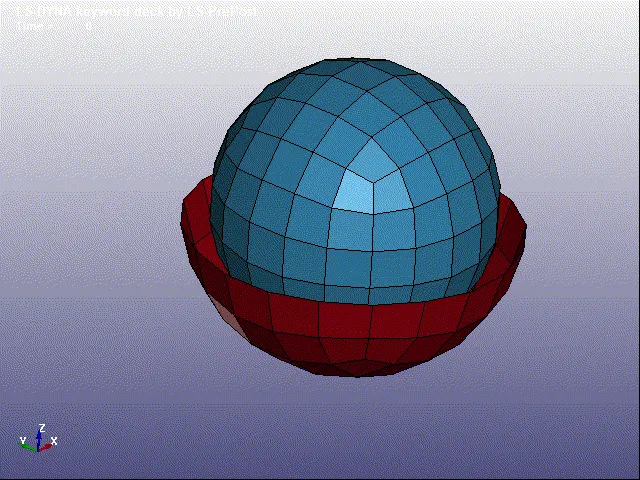
SPHERICAL JOINT USING DEFORMABLE BODY
- CNRB is created for bothe the inner and outer sphere shell
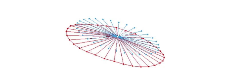
- Constrained Joint Cylindrical card is defined with the Coinciding nodes
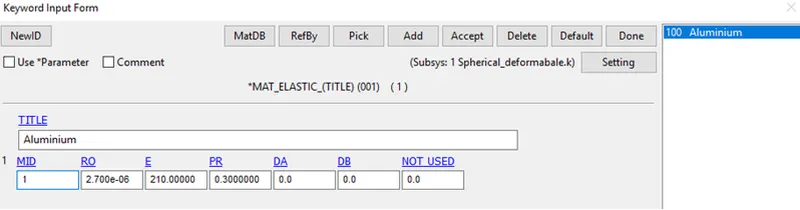
- MAT_ELASTIC card is defined with the Properties Of Aluminum
- All Other Keywords And Cards remains Unchanged and the Simulation is executed
CYLINDRICAL JOINT
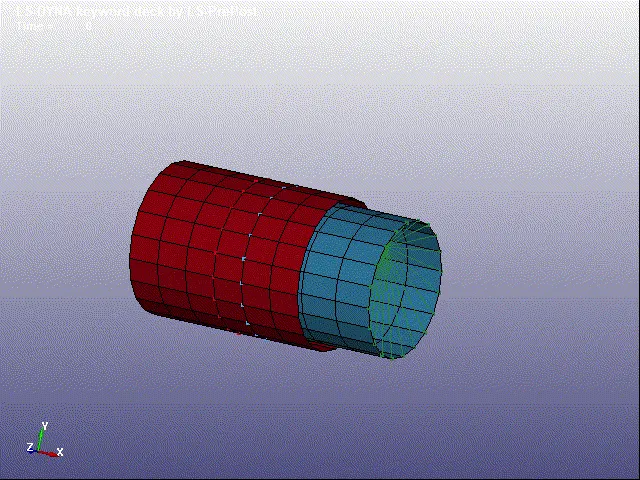
A cylindrical joint is a two-degrees of freedom kinematic pair used in mechanisms. Cylindrical joints provide single-axis sliding function as well as a single axis rotation, providing a way for two rigid bodies to translate and rotate freely. This can be pictured by an unsecured axle mounted on a chassis, as it may freely rotate and translate. An example of this would be the rotating rods of a table football.
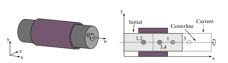
This joint is derived from the rotational joint by relaxing the constraints along the centerline. This joint admits relative rotation and translation along the centerline.
CYLINDRICAL JOINT USING RIGID BODY
- To create Cylindrical shell - Mesh > Shape Mesher > Sphere Shell
- One shell with Bigger Radius and another one with less smaller
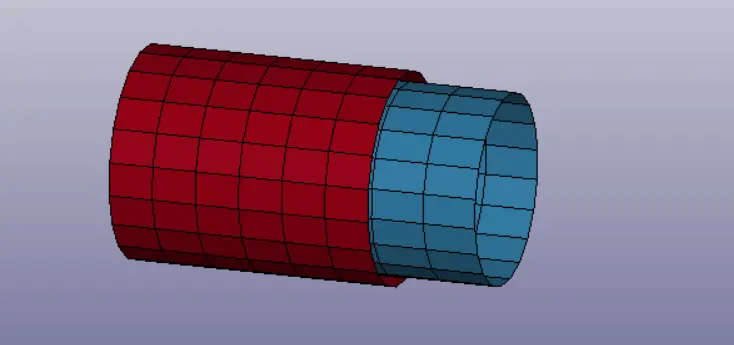
- Four nodes are created two each of both cylinders, to constrain it with parts
- CONSTRAINED_EXTRA_NODES_SET is used to connect nodes to part
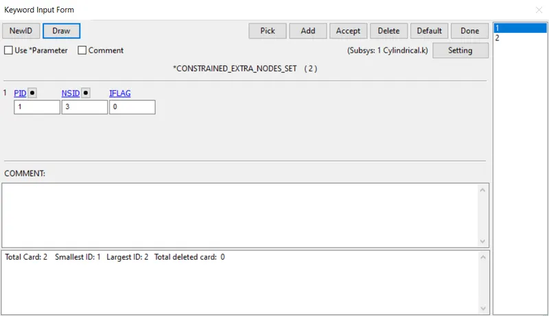
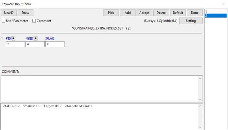
*CONSTRAINED_JOINT_CYLINDRICAL
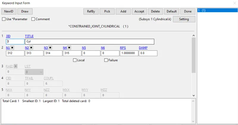
After this Velocity Rigid is given to Part 2 while part 1 is fixed using Spc
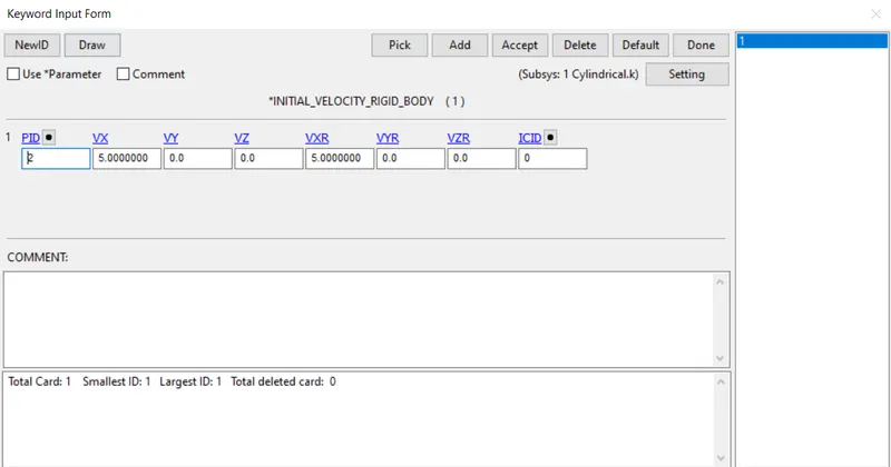
Results:
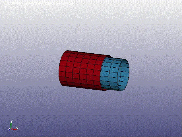
CYLINDRICAL JOINT USING DEFORMABLE BODY
1. CNRB is created to create cylindrical joint in deformable materials
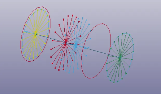
MATERIAL
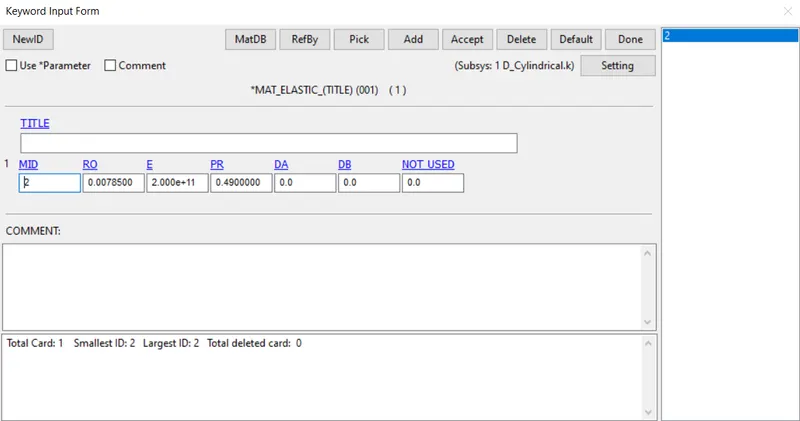
3. Initial velocity is specified
4. All other cards are similar to the above
Results:
TRANSLATIONAL JOINT
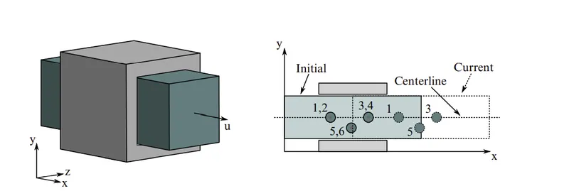
- The translational joint has only one translational degree of freedom and zero rotational degrees of freedom.
- This is a cylindrical joint with the third pair of off-centerline nodes which restrict rotation. Aside from translation along the centerline, the two rigid bodies are stuck together.
- Here the nodes (1,2) have coincided with each other. Similarly, the nodes (3,4) also (5,5) are coincided with each other as shown in the figure.
TRANSLATIONAJOINT USING RIGID BODY
Creating geometry for translational joint
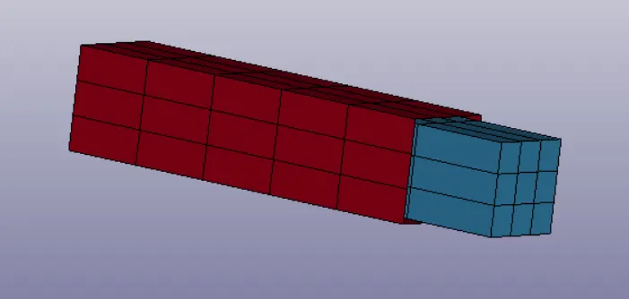
- A Box Shell is created >Shape Mesher>Entity>Box shell. Elements on both the sides of box is deleted.
CONSTRAINED EXTRA NODES
- 6 extra nodes are created and it is constrained to the parts.
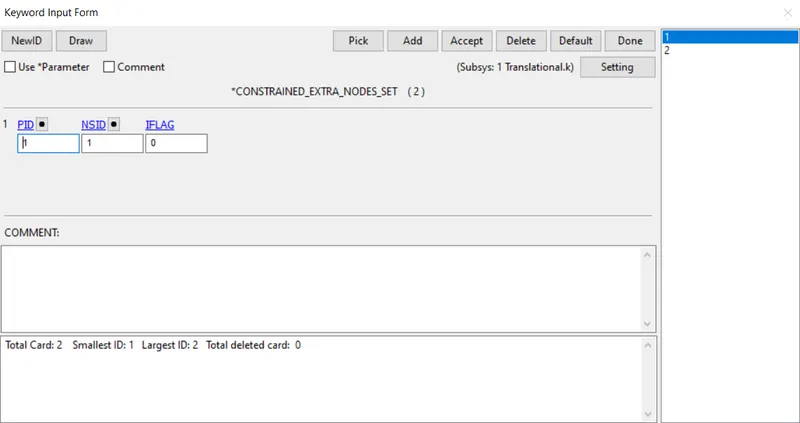
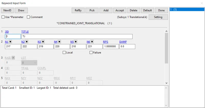

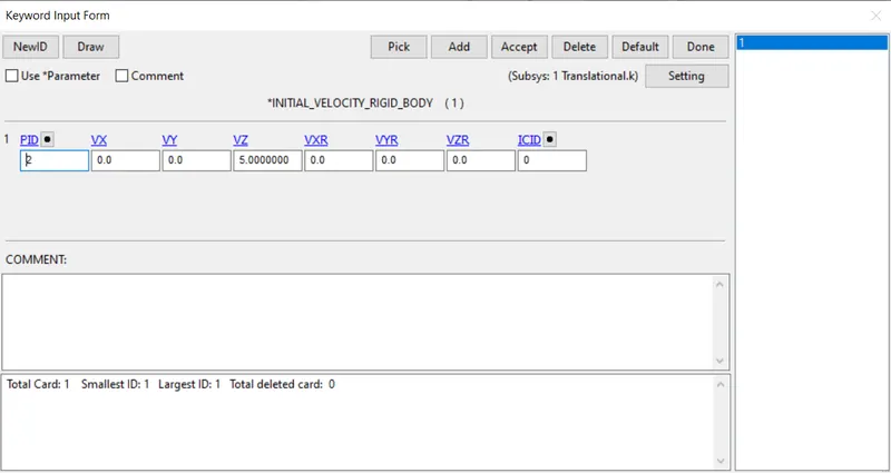
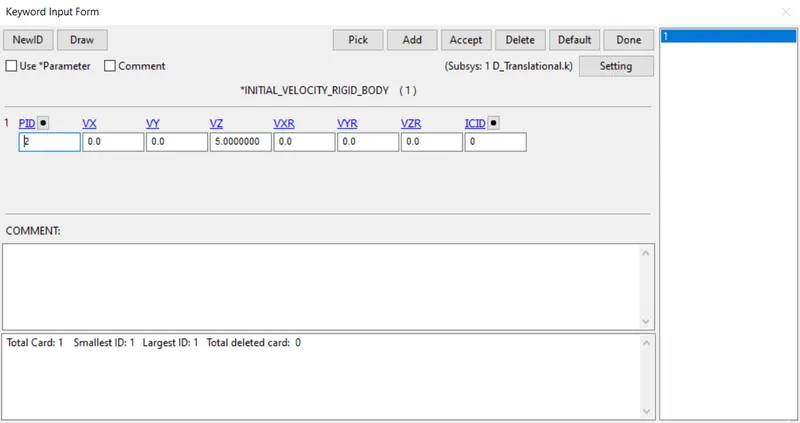
- Initial velocity rigid is specified
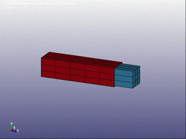
RESULT
- The model of translational joint is don using rigid body
TRANSLATIONAL JOINT USING DEFORMABLE BODY
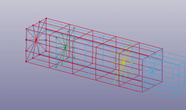
- 4 CNRB is created on two box parts
- *MAT_ELASTIC keyword for deformable material is assigned
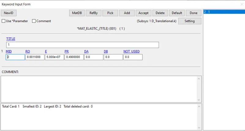
- CNRB Specification
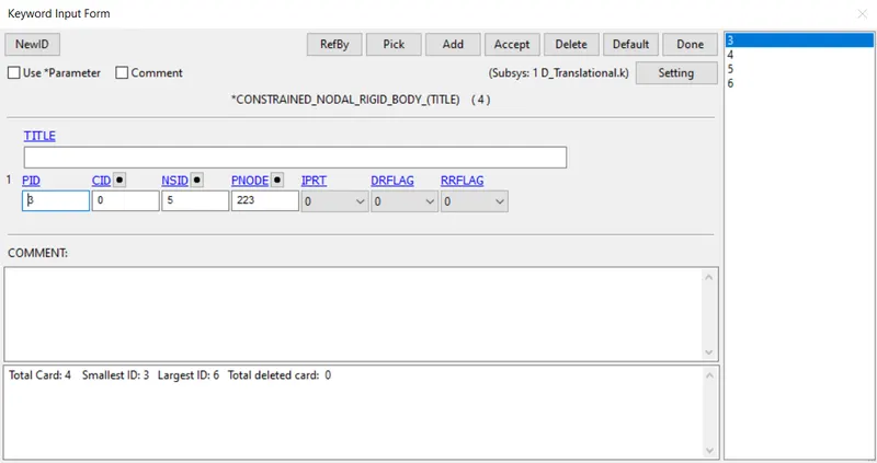
CNRB Translationajoint
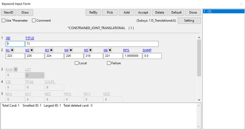
- The velocity is defined using the *INITAL_VELLOCITY card. and outer box is constrained
RESULT
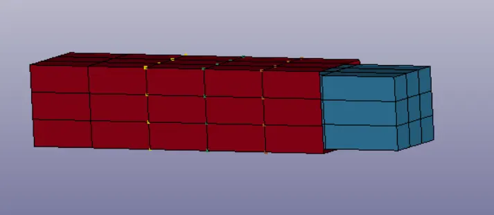
- The translational joint between two deformable bodies using CNRB's is shown below.