week-11 Joint creation and Demonstration
AIM:
To create revolute, spherical, cylindrical, and translational joints between 2 deformable and 2 rigid bodies.
Introduction:
Mechanical joints are designed to provide relative motion between two bodies in one degree of freedom and constrain the other 2 or more degrees of freedom. They provide rotational, cylindrical, revolutionary, and spherical movements depending on the usage.
Most of the joints are temporary and can be dismantled and assembled. Eg. threaded fasteners, keys, couplings, etc.
There are permanent joints that cannot be dismantled and then assembled. They are of 2 types depending on the force that holds them together. The forces of mechanical origin hold two components together by pure mechanical force. Eg. rivets. The components are joined by molecular forces. Eg. welding.
Procedure:
The common cards that had to be created when modeling revolute, spherical, cylindrical, and translational joints are-
1. Material card:
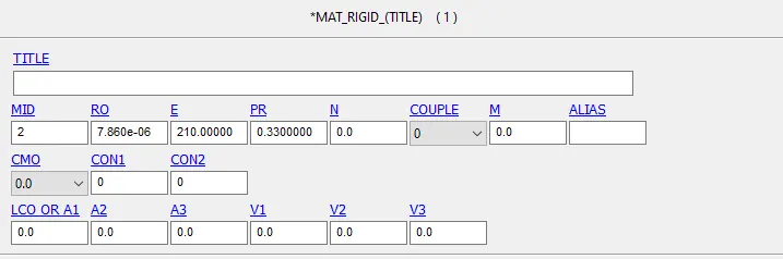
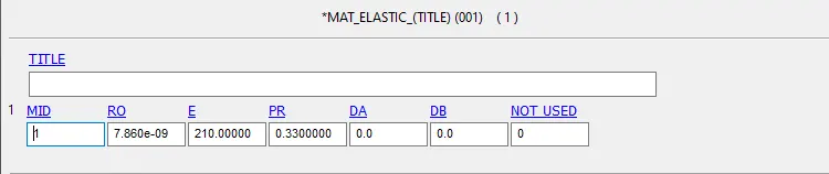
For performing two different conditions, we need to create the bodies with rigid material in 1 case and deformable elastic material in another case.
For Rigid body: MAT_RIGID
For deformable-body: MAT_ELASTIC
2. Section Card:
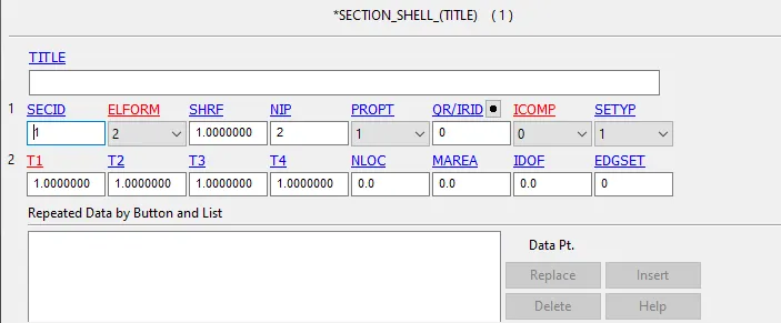
Section card defines the property of the shell elements that we use in the model. We can assign thickness, element formulation here.
3. Part card:
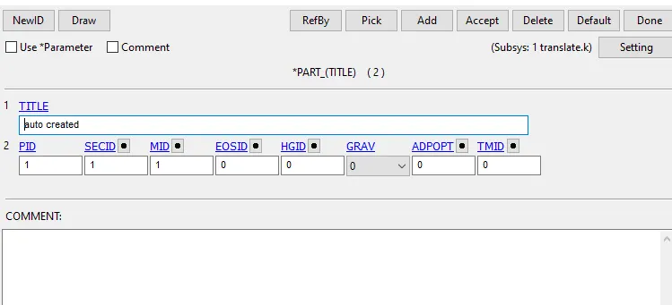
The part card is created when the model is generated. Assign section ID, material ID for the two parts in each case.
4. Constrained Extra Nodes Set:
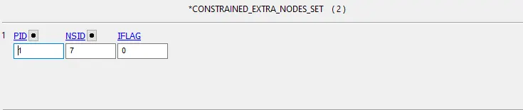
For Rigid body modeling, Keyword > Constrained > Extra_Node_Set are created and the NSID is assigned. The NSID contains the extra nodes responsible for the creation of mechanical joints. Respective nodes are assigned to relevant parts to form each mechanism.
5. Constrained Nodal Rigid Body:
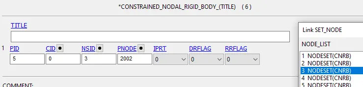
For deformable-body modeling, CNRBs are created instead of constrained extra nodes set.
Revolute Joints:
Procedure for deformable-body:
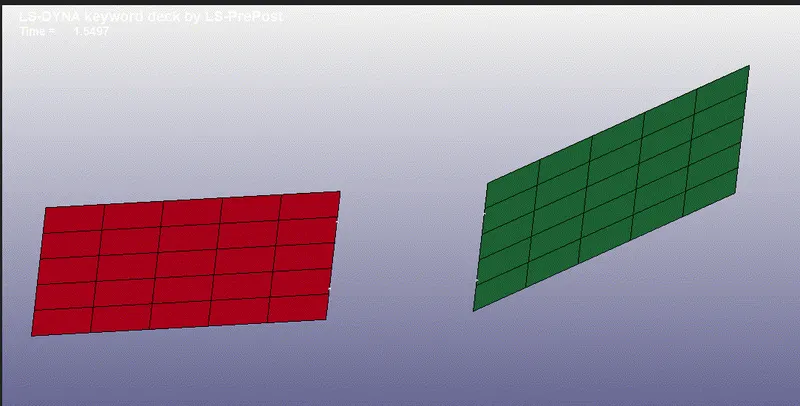
- Create a meshed plate as shown using the Mesh module > Shape Mesher > 4N Shell. Enter the coordinates for each point and hit create> accept.
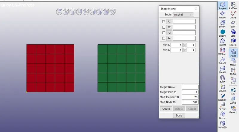
- Create 2 coinciding nodes 500,501 between the 2 parts on the bottom.
- Create another 2 coinciding nodes 503,504 between the 2 parts on the top.
- Create 4 CONSTRAINED_NODAL_RIGID_BODY for the nodes to respective parts as shown.
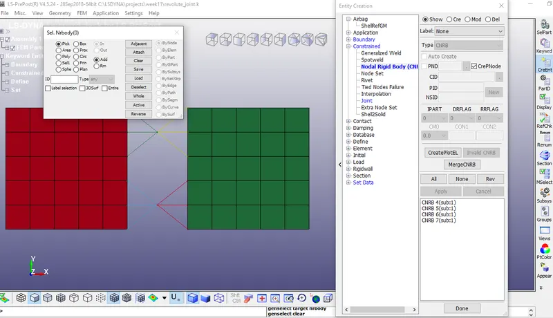
- Create CONSTRAINED > JOINT_REVOLUTE and assign the nodes 500, 503, 501, 502 to N1, N2, N3, N4.
- Assign MAT > 001_ELASTIC and assign the Section > Shell to the parts.
- Apply the INITIAL > VELOCITY NODE card and assign Vz value and DOF.
- Run the saved revolute_joint.k file in LS Run.
Procedure for the rigid body:
- Instead of CNRBs create CONSTRAINED > EXTRA_NODES_SET and assign the NSID and parts associated with the nodes.
- Assign the MAT > 020_RIGID for the parts.
- Create Initial > VELOCITY_RIGID_BODY
- The remaining cards are the same as the previous model.
- Run the model with LS Run.
- The simulation from the binary D3 plot file will be the same as the previous case.
Spherical joint:
Procedure for deformable joint:
- Create a meshed sphere using Mesh > Shape Mesher > Sphere Shell > Radius 20.
- Create another big sphere with the same center point and delete the elements on the top as shown.
- Add all the common cards as shown above.
- Create 2 coinciding nodes at the center of the sphere.
- Create CNRBs as shown.
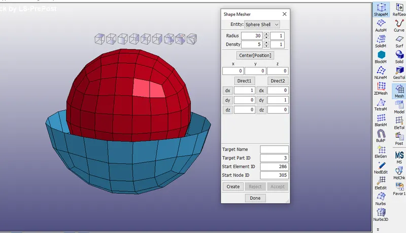
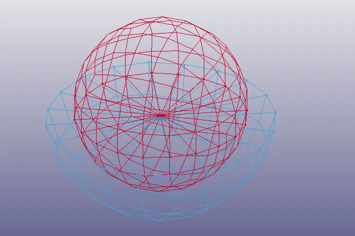
- Create a Constrained > Joint_Spherical and assign the 2 nodes on NI, N2.
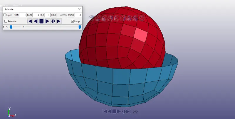
- Apply the INITIAL > VELOCITY NODE card and assign VRy, VRz values.
- Run the .k file with LS Run.
Procedure for the rigid body:
- Instead of CNRBs create CONSTRAINED > EXTRA_NODES_SET and assign the NSID and parts associated with the nodes.
- Assign the MAT > 020_RIGID for the parts.
- Create Initial > VELOCITY_RIGID_BODY
- The remaining cards are the same as the previous model.
- Run the model with LS Run.
- The simulation from the binary D3 plot file will be the same as the previous case.
Cylindrical Joint
Procedure for deformable joint:
- Create a long meshed cylinder using Mesh > Shape Mesher > Cylinder Shell > Radius 20.
- Create another short cylinder with a larger diameter as shown.
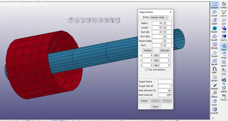
- Create 2 coinciding nodes at the center front and 2 coinciding nodes at the center back.
- Create CNRBs with the nodes as center points to each parts.
- 2 CNRBs entities on front and 2 at the back.
- Create CONSTRAINED > JOINT_CYLINDRICAL and assign the nodes to N1, N2, N3, N4.
- Apply the INITIAL > VELOCITY NODE card
- Run the .k file on LS Run.
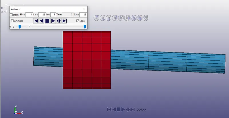
Procedure for the rigid body:
- Instead of CNRBs create CONSTRAINED > EXTRA_NODES_SET and assign the NSID and parts associated with the nodes.
- Assign the MAT > 020_RIGID for the parts.
- Create Initial > VELOCITY_RIGID_BODY
- The remaining cards are the same as the previous model.
- Run the model with LS Run.
- The simulation from the binary D3 plot file will be the same as the previous case.
Translational Joint
Procedure for deformable joint:
- Create a long meshed box using Mesh > Shape Mesher > Box Shell.
- Create another short meshed box with a larger diameter as shown.
- Create 2 coinciding nodes in front of the outer box and 2 coinciding nodes at the back of the outer box.
- Create another pair of coinciding nodes a little below the previous node's axis at the center of the outer box.
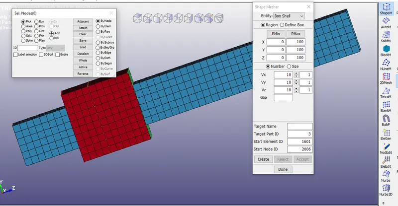
- Create CNRBs as shown on all 6 nodes.
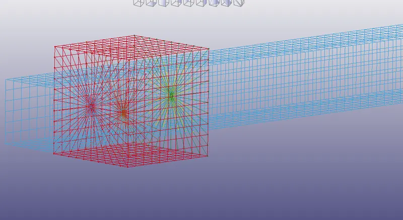
- Create CONSTRAINED > JOINT_TRANSLATIONAL card and assign all the nodes to N1, N2, N3, N4, N5, N6.
- Apply the INITIAL > VELOCITY NODE card and add Vx value as 15.
Procedure for the rigid body:
- Instead of CNRBs create CONSTRAINED > EXTRA_NODES_SET and assign the NSID and parts associated with the nodes.
- Assign the MAT > 020_RIGID for the parts.
- The remaining cards are the same as the previous model.
- Create Initial > VELOCITY_RIGID_BODY and assign DOF and Vx values.
- Run the model with LS Run.
- The simulation from the binary D3 plot file will be the same as the previous case.
MODEL LINK: https://drive.google.com/drive/folders/1KzbVFta0FsIDqeifxelINpUecuT5hO24?usp=sharing
CONCLUSION:
- The parts have been modeled in LS Dyna prepost.
- The nodes are assigned to respective Constrained Joint cards.
- The simulation is run in LS Run.
- The revolute, spherical, cylindrical, and translational joint mechanism is validated for rigid and deformable bodies in LS prepost binary d3plot.