week-11 Joint creation and Demonstration
TITLE: JOINR CREATION AND DEMONSTRATION
OBJECTIVE: To create different joint like spherical, revolute, translational and cylindrical in Ls-Dyna.
Common Procedure:
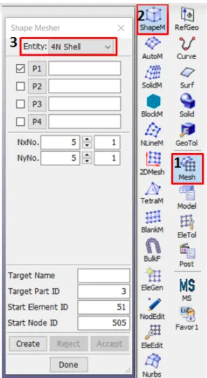
- Geometry is created using Mesh->Shape mesher option.
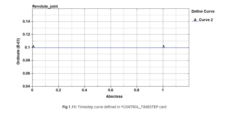
- Few keywords are commonly used in all the joints like MAT,SECTION, Control_Termination, Control_timestep, Database binary_D3plot. Here the curve used to define the timestep is as below to keep the constant timestep of simulation.
- SPHERICAL JOINTS
- Spherical joints have only one rotational degrees of freedom (DOF) whereas translational motion is constrained. These joints require only one pair of common nodes for joint creation.
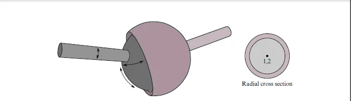
- At first Spheres were constructed using geometry mesh option.
- Two coinciding nodes a put on cnetre using node edit option.
- Then I use CONSTRAINED JOINT SPHERICAL key word to create spherical joint.
- After that I put all the necessary boundary condtions and run the simulation.
Animation Video:
2. REVOLUTE JOINTS
- Revolute joints: Formed of pair of two sets of coinciding nodes in between. The rotational motion is only allowed along the axis formed by two pair of coinciding nodes.
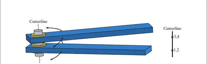
- Here two types of joints are created one is rifid body and another one is deformable body revolute joint.
- In both the cases geometry will be similar.
- Geometry is created using shape mesher option.
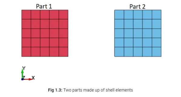
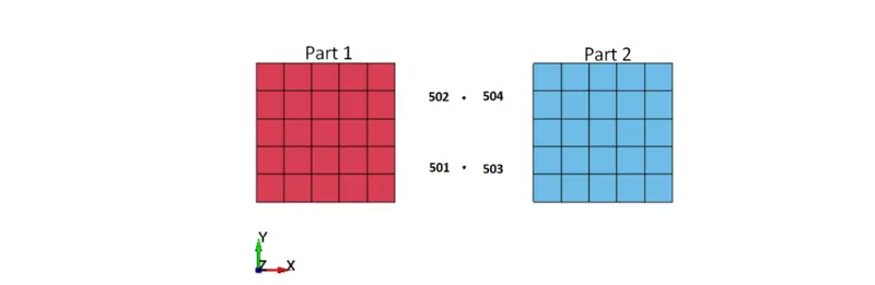
- Above are the two plates created for the demonstration purpose.
- Now I create four nodes between the two plates using create nodes option.
- These four nodes much coincide with each other.
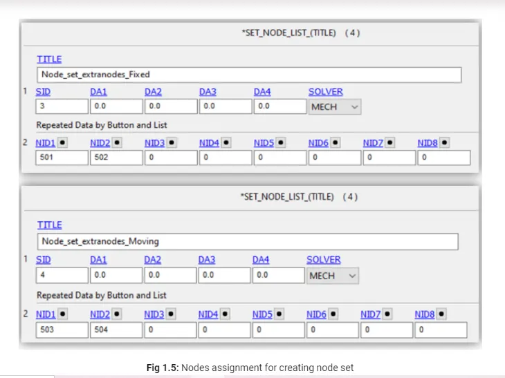
- Now I create nodes set where I kept node 501 and 502 to one set and 503 and 504 to other set.
- Now I assign CONTRAINED EXTRA NODE SET card to assign the node sets to parts.
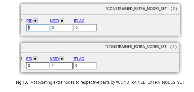
- Node 501 and 502 must assign to part 1 and 503 and 504 assign to part 2.
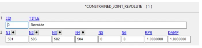
- CONSTRAIN REVOLUTE JOINT is used to denote the revolute joint.
- Now boundary conditions are put up to run the simulation.
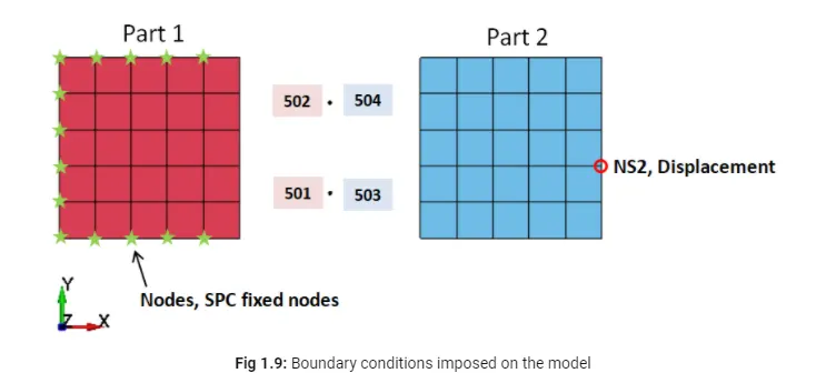
- SPC set are used to fix nodes in part 1 and displacement is given to a node in part2.
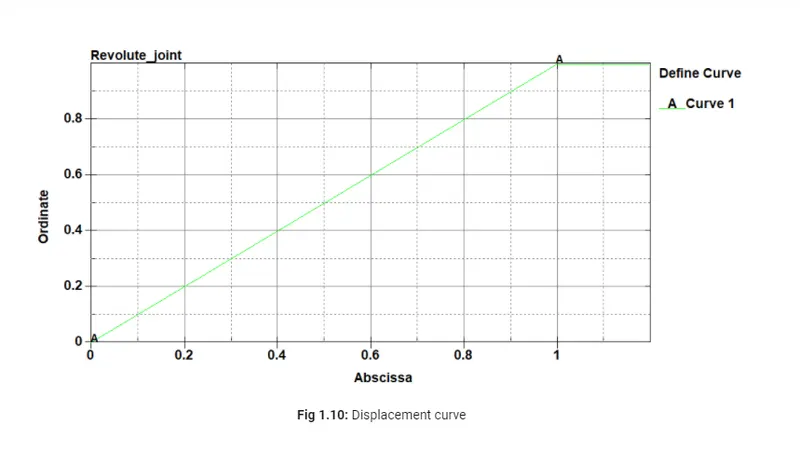
- Displacement curve is provided.
- Control timestep is used.
- Revolute joint for deformale bodies.
- In this part there is some change in the node option here CNRB(constrain nodal rigid body) are used to connect the nodes with the parts.
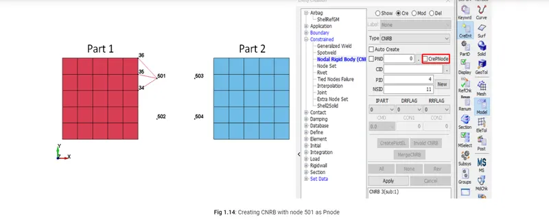
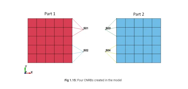
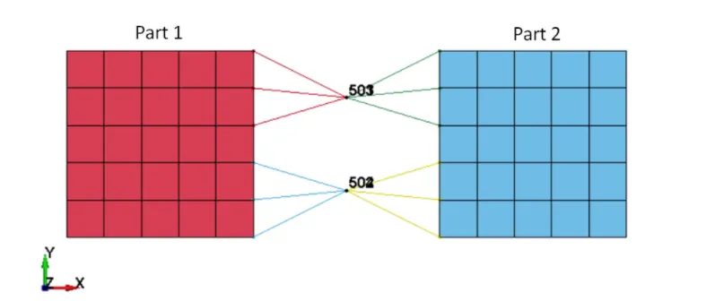
- Two nodes are coincide with each other.
- CONTRAINED JOINT REVOULTE is used for revolute joint.
- After that all the boundary conditions are set as above and run the simulation.
ANIMATION VIDEO:
3. CYLINDRICAL JOINTS
- Here two cylinders are created using Mesh->Shape mesher option.
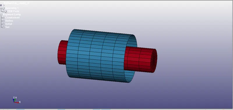
- Two coincident node pairs along the centre axis of the body. This can be done using extra nodes card.
- Create cylindrical joint using Constrained_Joint_Cylindrical and enter the node no.
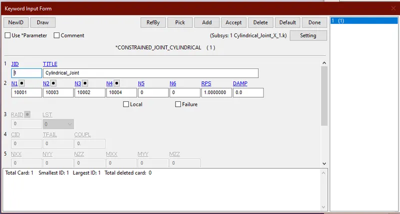
- The motion here is assigned using initial_velocity_rigidbody card.
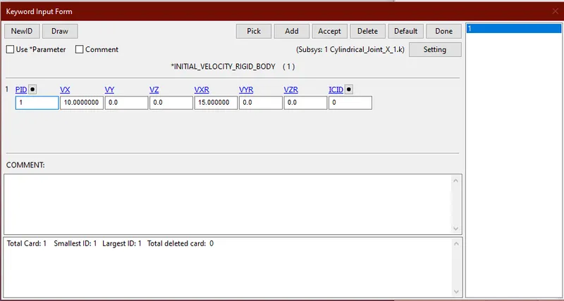
ANIMATION VIDEO:
4. TRANSLATIONAL JOINT
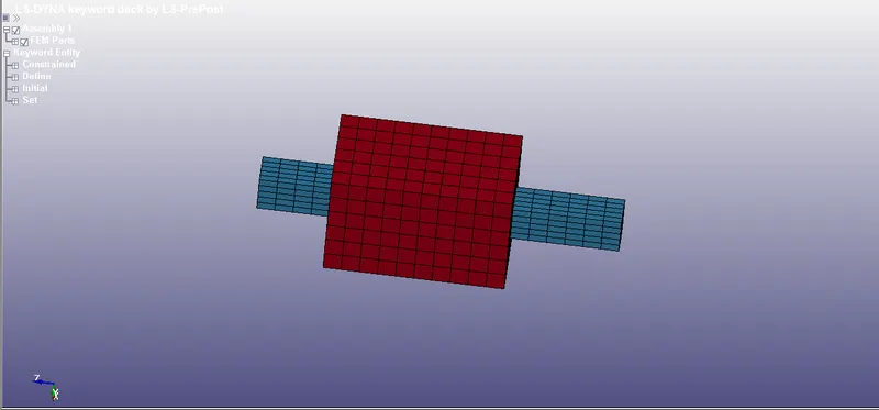
- Translational Joint follows the same procedure as cylindrical joint with additional pair of coincident nodes to restrict rotation. The geometry is created using curve and extrude options and meshed using auto mesher.
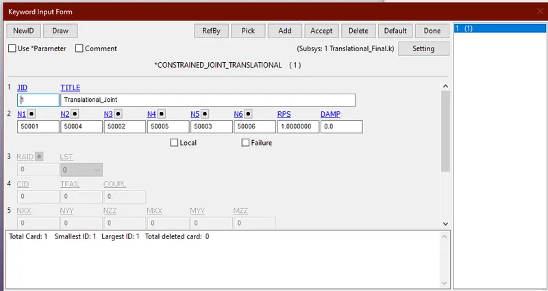
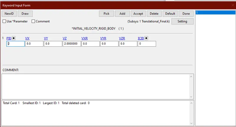
- The motion here is assigned using initial_velocity_rigidbody
ANIMATION VIDEO:
CONCLUSION:
- In this assignment I learnt about the geometry creation using LSDYNA.
- Creating different cards for the joints,rigid as well as deformable.
- Creating CNRBS to create the joints.
- Four different kinds of joints were created and simulation was performed.